Difference between revisions of "Lazarus on Raspberry Pi/de"
Jwdietrich (talk | contribs) (Erste Vorab-Version einer deutschen Fassung) |
Jwdietrich (talk | contribs) |
||
| Line 12: | Line 12: | ||
===Einfache Installation unter Raspbian=== | ===Einfache Installation unter Raspbian=== | ||
| − | + | Lazarus und Free Pascal können unter Raspbian OS schnell und einfach installiert werden. Es ist dafür nur nötig, ein Terminal-Fenster zu öffnen und die folgenden Kommandos einzugeben: | |
<syntaxhighlight> | <syntaxhighlight> | ||
| Line 21: | Line 21: | ||
</syntaxhighlight> | </syntaxhighlight> | ||
| − | + | Damit wird, natürlich unter der Voraussetzung einer funktionierenden Netzwerkverbindung, eine vorkompilierte Lazarus-Version auf dem Raspberry Pi installiert. Die Installation kann, je nach Version und Netzwerkgeschwindigkeit, etwa 30 Minuten erfordern, sie läuft aber überwiegend automatisch ab. Nach der Installation kann Lazarus direkt über das "Programming"-Untermenü des LXDE Startmenüs gestartet werden. | |
===Übersetzen aus den Quelltexten=== | ===Übersetzen aus den Quelltexten=== | ||
| − | + | Alternativ kann Lazarus auch aus den Subversion-Quelltexten übersetzt werden. Einzelheiten sind unter [http://www.michellcomputing.co.uk/blog/2012/11/lazarus-on-the-raspberry-pi/ Michell Computing: Lazarus on the Raspberry Pi] beschrieben. | |
<gallery> | <gallery> | ||
| − | File:Lazarus on Raspberry Pi.jpg|Lazarus | + | File:Lazarus on Raspberry Pi.jpg|Lazarus auf dem Raspberry Pi |
| − | File:rpi gpio pins.png| | + | File:rpi gpio pins.png|Nummerierung der GPIO-Anschlüsse |
</gallery> | </gallery> | ||
Revision as of 13:23, 30 April 2013
│
Deutsch (de) │
English (en) │
español (es) │
suomi (fi) │
中文(中国大陆) (zh_CN) │

Der Raspberry Pi ist ein kreditkartengroßer Einplatinenrechner. Er wurde in Großbritannien von der Raspberry Pi Foundation mit dem ursprünglichen Ziel entwickelt, den grundlegenden Informatikunterricht in Schulen zu fördern. Raspberry Pis können aber nicht nur für die Ausbildung, sondern für die unterschiedlichsten Zwecke, z. B. als Medienserver, Robotersteuerungen und für die Regelungstechnik eingesetzt werden.
Die Raspberry Pi Foundation empfiehlt als Standard-Betriebssystem Raspbian Wheezy. Alternative Betriebssysteme für den RPI sind z. B. RISC OS und verschiedene Linux-Distributionen, einschließlich Android.
Lazarus läuft nativ unter dem Betriebssystem Raspbian.
Lazarus installieren und/oder compilieren
Einfache Installation unter Raspbian
Lazarus und Free Pascal können unter Raspbian OS schnell und einfach installiert werden. Es ist dafür nur nötig, ein Terminal-Fenster zu öffnen und die folgenden Kommandos einzugeben:
  sudo apt-get update
  sudo apt-get upgrade
  sudo apt-get install fpc
  sudo apt-get install lazarus
Damit wird, natürlich unter der Voraussetzung einer funktionierenden Netzwerkverbindung, eine vorkompilierte Lazarus-Version auf dem Raspberry Pi installiert. Die Installation kann, je nach Version und Netzwerkgeschwindigkeit, etwa 30 Minuten erfordern, sie läuft aber überwiegend automatisch ab. Nach der Installation kann Lazarus direkt über das "Programming"-Untermenü des LXDE Startmenüs gestartet werden.
Übersetzen aus den Quelltexten
Alternativ kann Lazarus auch aus den Subversion-Quelltexten übersetzt werden. Einzelheiten sind unter Michell Computing: Lazarus on the Raspberry Pi beschrieben.
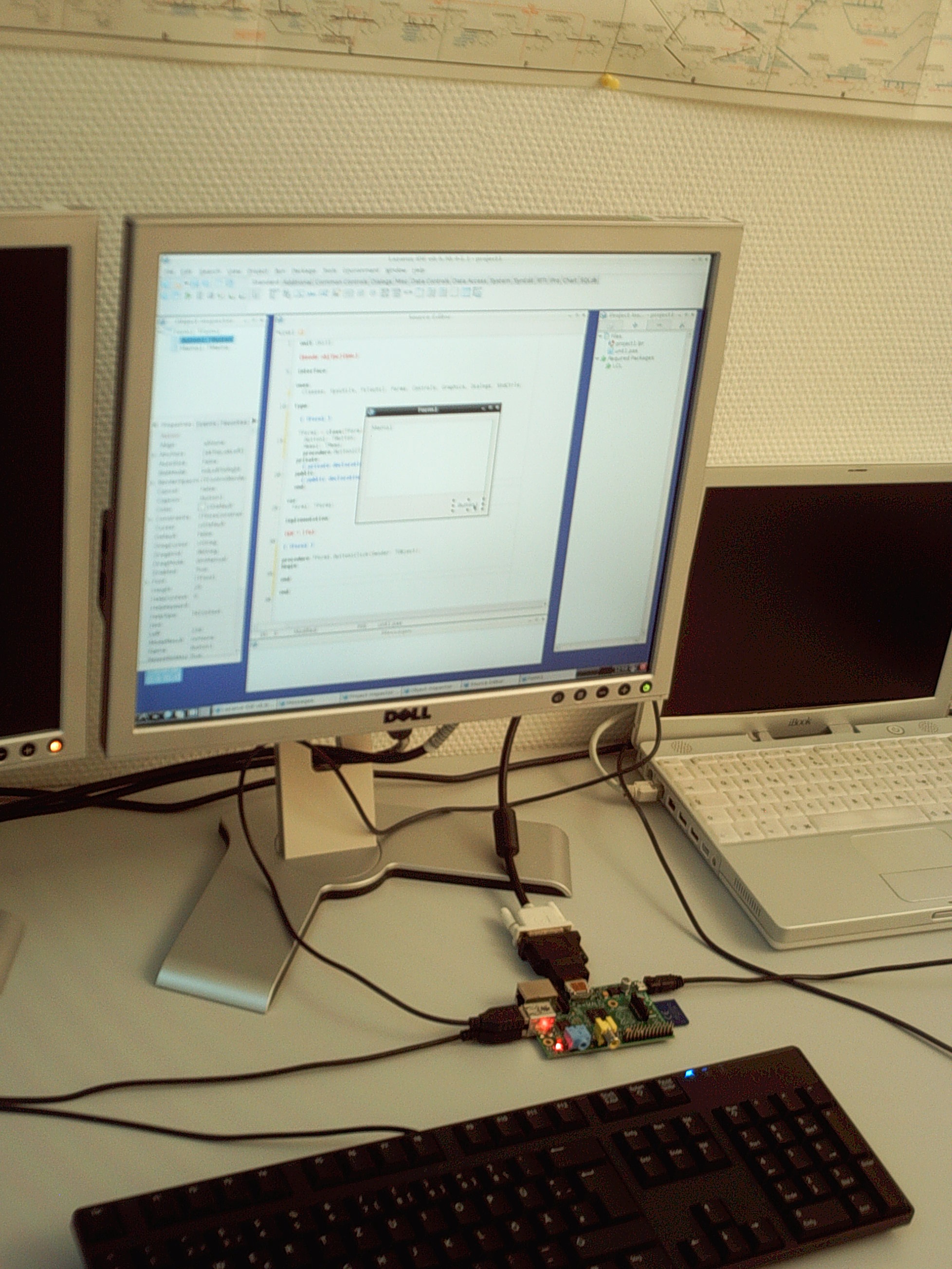
Lazarus auf dem Raspberry Pi
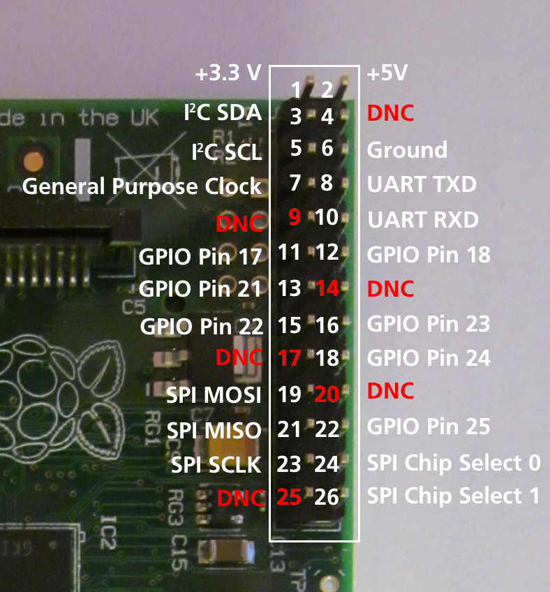
Nummerierung der GPIO-Anschlüsse


Zugriff auf externe Hardware

One of the goals in the development of Raspberry Pi was to facilitate effortless access to external devices like sensors and actuators. There are three ways to access the IO facilities from Lazarus and Free Pascal:
- Direct access using the BaseUnix unit
- Access through encapsulated shell calls
- Access through the wiringPi library.
1. Nativer Hardware-Zugriff


This method provides access to external hardware that doesn't require additional libraries. The only requirement is the BaseUnix library that is part of Free Pascal's RTL.
Schalten eines Gerätes über den GPIO-Port
The following example lists a simple program that controls the GPIO pin 17 as output to switch an LED, transistor or relais. This program contains a ToggleBox with name GPIO17ToggleBox and for logging return codes a TMemo called LogMemo.
For the example, the anode of a LED has been connected with Pin 11 on the Pi's connector (corresponding to GPIO pin 17 of the BCM2835 SOC) and the LED's cathode was wired via a 68 Ohm resistor to pin 6 of the connector (GND) as previously described by Upton and Halfacree. Subsequently, the LED may be switched on and off with the application's toggle box.
The code requires to be run as root, i.e. either from a root account (not recommended) or via su.
Controlling unit:
unit Unit1;

{Demo application for GPIO on Raspberry Pi}
{Inspired by the Python input/output demo application by Gareth Halfacree}
{written for the Raspberry Pi User Guide, ISBN 978-1-118-46446-5}

{$mode objfpc}{$H+}

interface

uses
  Classes, SysUtils, FileUtil, Forms, Controls, Graphics, Dialogs, StdCtrls,
  Unix, BaseUnix;

type

  { TForm1 }

  TForm1 = class(TForm)
    LogMemo: TMemo;
    GPIO17ToggleBox: TToggleBox;
    procedure FormActivate(Sender: TObject);
    procedure FormClose(Sender: TObject; var CloseAction: TCloseAction);
    procedure GPIO17ToggleBoxChange(Sender: TObject);
  private
    { private declarations }
  public
    { public declarations }
  end;

const
  PIN_17: PChar = '17';
  PIN_ON: PChar = '1';
  PIN_OFF: PChar = '0';
  OUT_DIRECTION: PChar = 'out';

var
  Form1: TForm1;
  gReturnCode: longint; {stores the result of the IO operation}

implementation

{$R *.lfm}

{ TForm1 }

procedure TForm1.FormActivate(Sender: TObject);
var
  fileDesc: integer;
begin
  { Prepare SoC pin 17 (pin 11 on GPIO port) for access: }
  try
    fileDesc := fpopen('/sys/class/gpio/export', O_WrOnly);
    gReturnCode := fpwrite(fileDesc, PIN_17[0], 2);
    LogMemo.Lines.Add(IntToStr(gReturnCode));
  finally
    gReturnCode := fpclose(fileDesc);
    LogMemo.Lines.Add(IntToStr(gReturnCode));
  end;
  { Set SoC pin 17 as output: }
  try
    fileDesc := fpopen('/sys/class/gpio/gpio17/direction', O_WrOnly);
    gReturnCode := fpwrite(fileDesc, OUT_DIRECTION[0], 3);
    LogMemo.Lines.Add(IntToStr(gReturnCode));
  finally
    gReturnCode := fpclose(fileDesc);
    LogMemo.Lines.Add(IntToStr(gReturnCode));
  end;
end;

procedure TForm1.FormClose(Sender: TObject; var CloseAction: TCloseAction);
var
  fileDesc: integer;
begin
  { Free SoC pin 17: }
  try
    fileDesc := fpopen('/sys/class/gpio/unexport', O_WrOnly);
    gReturnCode := fpwrite(fileDesc, PIN_17[0], 2);
    LogMemo.Lines.Add(IntToStr(gReturnCode));
  finally
    gReturnCode := fpclose(fileDesc);
    LogMemo.Lines.Add(IntToStr(gReturnCode));
  end;
end;

procedure TForm1.GPIO17ToggleBoxChange(Sender: TObject);
var
  fileDesc: integer;
begin
  if GPIO17ToggleBox.Checked then
  begin
    { Swith SoC pin 17 on: }
    try
      fileDesc := fpopen('/sys/class/gpio/gpio17/value', O_WrOnly);
      gReturnCode := fpwrite(fileDesc, PIN_ON[0], 1);
      LogMemo.Lines.Add(IntToStr(gReturnCode));
    finally
      gReturnCode := fpclose(fileDesc);
      LogMemo.Lines.Add(IntToStr(gReturnCode));
    end;
  end
  else
  begin
    { Switch SoC pin 17 off: }
    try
      fileDesc := fpopen('/sys/class/gpio/gpio17/value', O_WrOnly);
      gReturnCode := fpwrite(fileDesc, PIN_OFF[0], 1);
      LogMemo.Lines.Add(IntToStr(gReturnCode));
    finally
      gReturnCode := fpclose(fileDesc);
      LogMemo.Lines.Add(IntToStr(gReturnCode));
    end;
  end;
end;

end.
Main program:
program io_test;

{$mode objfpc}{$H+}

uses
  {$IFDEF UNIX}{$IFDEF UseCThreads}
  cthreads,
  {$ENDIF}{$ENDIF}
  Interfaces, // this includes the LCL widgetset
  Forms, Unit1
  { you can add units after this };

{$R *.res}

begin
  Application.Initialize;
  Application.CreateForm(TForm1, Form1);
  Application.Run;
end.
Den Status eines Anschlusses lesen


Of course it is also possible to read the status of e.g. a switch that is connected to the GPIO port.
The following simple example is very similar to the previous one. It controls the GPIO pin 18 as input for a binary device like a switch, transistor or relais. This program contains a CheckBox with name GPIO18CheckBox and for logging return codes a TMemo called LogMemo.
For the example, one pole of a push-button has been connected to Pin 12 on the Pi's connector (corresponding to GPIO pin 18 of the BCM2835 SOC) and via a 10 kOhm pull-up resistor with pin 1 (+3.3V, see wiring diagram). The other pole has been wired to pin 6 of the connector (GND). The program senses the status of the button and correspondingly switches the CheckBox on or off, respectively.
Note that the potential of pin 18 is high if the button is released (by virtue of the connection to pin 1 via the pull-up resistor) and low if it is pressed (sinced in this situation pin 18 is connected to GND via the switch). Therefore, the GPIO pin signals 0 if the button is pressed and 1 if it is released.
This program has again to be executed as root.
Controlling unit:
unit Unit1;

{Demo application for GPIO on Raspberry Pi}
{Inspired by the Python input/output demo application by Gareth Halfacree}
{written for the Raspberry Pi User Guide, ISBN 978-1-118-46446-5}

{This application reads the status of a push-button}

{$mode objfpc}{$H+}

interface

uses
  Classes, SysUtils, FileUtil, Forms, Controls, Graphics, Dialogs, StdCtrls,
  ButtonPanel, Unix, BaseUnix;

type

  { TForm1 }

  TForm1 = class(TForm)
    ApplicationProperties1: TApplicationProperties;
    GPIO18CheckBox: TCheckBox;
    LogMemo: TMemo;
    procedure ApplicationProperties1Idle(Sender: TObject; var Done: Boolean);
    procedure FormActivate(Sender: TObject);
    procedure FormClose(Sender: TObject; var CloseAction: TCloseAction);
  private
    { private declarations }
  public
    { public declarations }
  end;

const
  PIN_18: PChar = '18';
  IN_DIRECTION: PChar = 'in';

var
  Form1: TForm1;
  gReturnCode: longint; {stores the result of the IO operation}

implementation

{$R *.lfm}

{ TForm1 }

procedure TForm1.FormActivate(Sender: TObject);
var
  fileDesc: integer;
begin
  { Prepare SoC pin 18 (pin 12 on GPIO port) for access: }
  try
    fileDesc := fpopen('/sys/class/gpio/export', O_WrOnly);
    gReturnCode := fpwrite(fileDesc, PIN_18[0], 2);
    LogMemo.Lines.Add(IntToStr(gReturnCode));
  finally
    gReturnCode := fpclose(fileDesc);
    LogMemo.Lines.Add(IntToStr(gReturnCode));
  end;
  { Set SoC pin 18 as input: }
  try
    fileDesc := fpopen('/sys/class/gpio/gpio18/direction', O_WrOnly);
    gReturnCode := fpwrite(fileDesc, IN_DIRECTION[0], 2);
    LogMemo.Lines.Add(IntToStr(gReturnCode));
  finally
    gReturnCode := fpclose(fileDesc);
    LogMemo.Lines.Add(IntToStr(gReturnCode));
  end;
end;

procedure TForm1.ApplicationProperties1Idle(Sender: TObject; var Done: Boolean);
var
  fileDesc: integer;
  buttonStatus: string[1] = '1';
begin
  try
    { Open SoC pin 18 (pin 12 on GPIO port) in read-only mode: }
    fileDesc := fpopen('/sys/class/gpio/gpio18/value', O_RdOnly);
    if fileDesc > 0 then
    begin
      { Read status of this pin (0: button pressed, 1: button released): }
      gReturnCode := fpread(fileDesc, buttonStatus[1], 1);
      LogMemo.Lines.Add(IntToStr(gReturnCode) + ': ' + buttonStatus);
      LogMemo.SelStart := Length(LogMemo.Lines.Text) - 1;
      if buttonStatus = '0' then
        GPIO18CheckBox.Checked := true
      else
        GPIO18CheckBox.Checked := false;
    end;
  finally
    { Close SoC pin 18 (pin 12 on GPIO port) }
    gReturnCode := fpclose(fileDesc);
    LogMemo.Lines.Add(IntToStr(gReturnCode));
    LogMemo.SelStart := Length(LogMemo.Lines.Text) - 1;
  end;
end;

procedure TForm1.FormClose(Sender: TObject; var CloseAction: TCloseAction);
var
  fileDesc: integer;
begin
  { Free SoC pin 18: }
  try
    fileDesc := fpopen('/sys/class/gpio/unexport', O_WrOnly);
    gReturnCode := fpwrite(fileDesc, PIN_18[0], 2);
    LogMemo.Lines.Add(IntToStr(gReturnCode));
  finally
    gReturnCode := fpclose(fileDesc);
    LogMemo.Lines.Add(IntToStr(gReturnCode));
  end;
end;

end.
The main program is identical to that of the example from above.
2. Hardware-Zugriff über gekapselte Shell-Aufrufe
Another way to access the hardware is by encapsulating terminal commands. This is achieved by using the fpsystem function. This method gives access to functions that are not supported by the BaseUnix unit. The following code implements a program that has the same functionality as the program resulting from the first listing above.
Controlling unit:
unit Unit1;

{Demo application for GPIO on Raspberry Pi}
{Inspired by the Python input/output demo application by Gareth Halfacree}
{written for the Raspberry Pi User Guide, ISBN 978-1-118-46446-5}

{$mode objfpc}{$H+}

interface

uses
  Classes, SysUtils, FileUtil, Forms, Controls, Graphics, Dialogs, StdCtrls, Unix;

type

  { TForm1 }

  TForm1 = class(TForm)
    LogMemo: TMemo;
    GPIO17ToggleBox: TToggleBox;
    procedure FormActivate(Sender: TObject);
    procedure FormClose(Sender: TObject; var CloseAction: TCloseAction);
    procedure GPIO17ToggleBoxChange(Sender: TObject);
  private
    { private declarations }
  public
    { public declarations }
  end;

var
  Form1: TForm1;
  gReturnCode: longint; {stores the result of the IO operation}

implementation

{$R *.lfm}

{ TForm1 }

procedure TForm1.FormActivate(Sender: TObject);
begin
  { Prepare SoC pin 17 (pin 11 on GPIO port) for access: }
  gReturnCode := fpsystem('echo "17" > /sys/class/gpio/export');
  LogMemo.Lines.Add(IntToStr(gReturnCode));
  { Set SoC pin 17 as output: }
  gReturnCode := fpsystem('echo "out" > /sys/class/gpio/gpio17/direction');
  LogMemo.Lines.Add(IntToStr(gReturnCode));
end;

procedure TForm1.FormClose(Sender: TObject; var CloseAction: TCloseAction);
begin
  { Free SoC pin 17: }
  gReturnCode := fpsystem('echo "17" > /sys/class/gpio/unexport');
  LogMemo.Lines.Add(IntToStr(gReturnCode));
end;

procedure TForm1.GPIO17ToggleBoxChange(Sender: TObject);
begin
  if GPIO17ToggleBox.Checked then
  begin
    { Swith SoC pin 17 on: }
    gReturnCode := fpsystem('echo "1" > /sys/class/gpio/gpio17/value');
    LogMemo.Lines.Add(IntToStr(gReturnCode));
  end
  else
  begin
    { Switch SoC pin 17 off: }
    gReturnCode := fpsystem('echo "0" > /sys/class/gpio/gpio17/value');
    LogMemo.Lines.Add(IntToStr(gReturnCode));
  end;
end;

end.
The main program is identical to that of the example above. This program has to be executed with root privileges, too.
3. wiringPi-Prozeduren und Funktionen
Alex Schaller's wrapper unit for Gordon Henderson Arduino compatible wiringPi library provides a numbering scheme that resembles that of Arduino boards.
Function wiringPiSetup:longint: Initializes wiringPi system using the wiringPi pin numbering scheme.
Procedure wiringPiGpioMode(mode:longint): Initializes wiringPi system with the Broadcom GPIO pin numbering shceme.
Procedure pullUpDnControl(pin:longint; pud:longint): controls the internal pull-up/down resistors on a GPIO pin.
Procedure pinMode(pin:longint; mode:longint): sets the mode of a pin to either INPUT, OUTPUT, or PWM_OUTPUT.
Procedure digitalWrite(pin:longint; value:longint): sets an output bit.
Procedure pwmWrite(pin:longint; value:longint): sets an output PWM value between 0 and 1024.
Function digitalRead(pin:longint):longint: reads the value of a given Pin, returning 1 or 0.
Procedure delay(howLong:dword): waits for at least howLong milliseconds
Procedure delayMicroseconds(howLong:dword): waits for at least howLong microseconds
Function millis:dword: returns the number of milliseconds since the program called one of the wiringPiSetup functions
Literatur
- Eben Upton and Gareth Halfacree. Raspberry Pi User Guide. John Wiley and Sons, Chichester 2012, ISBN 111846446X