Developing with Graphics/it
│
Deutsch (de) │
English (en) │
español (es) │
français (fr) │
italiano (it) │
日本語 (ja) │
한국어 (ko) │
Nederlands (nl) │
português (pt) │
русский (ru) │
slovenčina (sk) │
中文(中国大陆) (zh_CN) │
中文(台灣) (zh_TW) │
Questa pagina descrive le classi e le tecniche di base riguardanti l'uso della grafica in Lazarus. Approfondimenti sono trattati in articoli più specifici.
Librerie
Librerie grafiche - qui si possono osservare le principali librerie utilizzabili per lo sviluppo.
Altri articoli di grafica
Disegno 2D
- ZenGL - libreria multi-piattaforma per lo sviluppo di giochi mediante OpenGL.
- BGRABitmap - Disegno di forme e bitmap con funzioni di trasparenza, accesso diretto ai pixel, ecc.
- LazRGBGraphics - Package per l'elaborazione veloce di immagini in memoria e per la manipolazione a livello di pixel (es. scan line).
- fpvectorial - Supporto per leggere, modificare e salvare immagini vettoriali.
- Double Gradient - Disegnare facilmente bitmap con 'doppio gradiente' e gradienti di 'grado n'.
- Gradient Filler - TGradientFiller é il miglior modo di creare gradienti di grado n personalizzati in Lazarus.
- PascalMagick - una API di semplice uso per interfacciarsi con ImageMagick, una suite multi-piattaforma free per creare, editare e comporre immagini bitmap.
- Sample Graphics - collezioni di grafica create con Lazarus e strumenti di disegno.
- Fast direct pixel access - confronto di velocità di alcuni metodi di accesso diretto ai pixel di immagini bitmap.
- AggPas - AggPas è la traduzione in Object Pascal nativo port della libreria Anti-Grain Geometry. Veloce e potente, con funzioni di disegno anti-aliased ed accuratezza al subpixel. Si può pensare ad AggPas come ad un motore di rendering che produce immagini in pixel, in memoria, a partire da dati vettoriali.
Disegno 3D
- GLScene - Porting della Libreria visuale 3D di OpenGL GLScene
- Castle Game Engine - Un motore 3D e 2D multi-piattaforma per giochi FPC/Lazarus (sito ufficiale)
Grafici
- TAChart - Componente per tracciamento di grafici in Lazarus
- PlotPanel - Componente per disegnare e tracciare grafici con effetti di animazione
- Perlin Noise - Un articolo sull'uso di Perlin Noise in applicazioni LCL.
Introduzione al modello Grafico della LCL
La Lazarus Component Library (LCL) fornisce due tipi di classi di disegno: native e non-native. Le classi native sono il modo più tradizionale per implementare grafica nella LCL e sono le più importanti; le classi non native possono essere considerate come complementari. Le classi native si trovano, per la maggior parte, nell'unità Graphics della LCL. Esse sono: TBitmap, TCanvas, TFont, TBrush, TPen, TPortableNetworkGraphic, etc.
TCanvas è una classe in grado di eseguire disegni. Essa non può esistere da sola, bensì deve essere collegata a qualcosa di visibile (o almeno potenzialmente visibile), come un controllo visuale discendente da TControl, oppure deve essere collegata ad un buffer off-screen discendente da TRasterImage (TBitmap è quello usato più comunemente). TFont, TBrush and TPen descrivono come le varie operazioni di disegno saranno eseguite nel Canvas.
TRasterImage (usualmente utilizzata per via del suo discendente TBitmap) è un'area di memoria riservata per la tracciatura di disegni, ma è creata per assicurare la massima compatibilità con il Canvas nativo; pertanto in LCL-Gtk2 in X11 si trova localizzato nel server X11, il che rende l'accesso ai pixel tramite la proprietà Pixels estremamente lento. In Windows al contrario è molto veloce poiché Windows permette la creazione di immagine allocata localmente, che può ricevere disegni da un Canvas di Windows.
Oltre a queste vi sono pure classi non native localizzate nelle unità graphtype (TRawImage), intfgraphics (TLazIntfImage) e lazcanvas (TLazCanvas, esiste in Lazarus 0.9.31+). TRawImage è l'archivio e la descrizione di un'area di memoria che contiene un'immagine. TLazIntfImage è un'immagine agganciata a TRawImage che si incarica della conversione tra TFPColor e l'effetivo formato del pixel di TRawImage. TLazCanvas è un Canvas non-nativo che può disegnare un'immagine in un oggetto TLazIntfImage.
La principale differenza tra classi native e non native sta nel fatto che le prime possono avere una resa diversa su piattaforme diverse, dato che il disegno viene eseguito in ultima istanza dalla piattaforma sottostante. In particolare la velocitá di resa oltreché l'esatto aspetto finale delle immagini disegnate possono presentare differenze. Le classi non-native garantiscono invece risultati eguali e prestazioni accettabili su tutte le piattaforme.
Nel widgeset LCL-CustomDrawn le classi native sono implementate usando le non-native.
Tutte queste classi saranno meglio descritte nelle sezioni seguenti.
Lavorare con TCanvas
Drawing shapes
Drawing a rectangle
Many controls expose their canvas as a public Canvas property (or via an OnPaint event). Such controls include TForm, TPanel and TPaintBox. Let's use TForm as an example to demonstrate how to paint on a canvas.
Suppose we want to draw a red rectangle with a 5-pixel-thick blue border in the center of the form, and the the rectangle should be half the size of the form. For this purpose we must add code to the OnPaint event of the form. Never paint in an OnClick handler, because this painting is not persistent and will be erased whenever the operating system requests a repaint. Always paint in the OnPaint event!
The TCanvas method for painting a rectangle is named very logically: Rectangle(). You can pass rectangle's edge coordinates to the method either as four separate x/y values, or as a single TRect record. The fill color is determined by the color of the canvas's Brush, and the border color is given by the color of the canvas's Pen:
procedure TForm1.FormPaint(Sender: TObject);
var
  w, h: Integer;    // Width and height of the rectangle
  cx, cy: Integer;  // center of the form
  R: TRect;         // record containing the coordinates of the rectangle's left, top, right, bottom corners
begin
  // Calculate form center
  cx := Width div 2;
  cy := Height div 2;

  // Calculate the size of the rectangle
  w := Width div 2;
  h := Height div 2;

  // Calculate the corner points of the rectangle
  R.Left := cx - w div 2;
  R.Top := cy - h div 2;
  R.Right := cx + w div 2;
  R.Bottom := cy + h div 2;

  // Set the fill color
  Canvas.Brush.Color := clRed;
  Canvas.Brush.Style := bsSolid;

  // Set the border color
  Canvas.Pen.Color := clBlue;
  Canvas.Pen.Width := 5;
  Canvas.Pen.Style := psSolid;

  // Draw the rectangle
  Canvas.Rectangle(R);
end;
Drawing a circle
The canvas does not have a direct method to draw a circle. But there is a method to draw an ellipse. Knowing that a circle is a special case of an ellipse with equal half-axes we can draw a circle as follows:
procedure TForm1.FormPaint(Sender: TObject);
var
  radius: Integer;   // Radius of the circle
  center: TPoint;    // Center point of the circle
  R: TRect;          // Rectangle enclosing the circle
begin
  // Set the fill color
  Canvas.Brush.Color := clYellow;
  Canvas.Brush.Style := bsSolid;

  // Set the border color
  Canvas.Pen.Color := clBlue;
  Canvas.Pen.Width := 3;
  Canvas.Pen.Style := psSolid;

  // We want the circle to be centered in the form
  center.X := Width div 2;
  center.Y := Height div 2;

  // The diameter should be 90% of the width or the height, whichever is smaller.
  // The radius, then, is half of this value.
  if Width > Height then
    radius := round(Height * 0.45)
  else
    radius := round(Width * 0.45);

  // The circle then will be enclosed by the rectangle between center.X +/- radius
  // and center.Y +/- radius
  R := Rect(center.X - radius, center.Y - radius, center.X + radius, center.Y + radius);

  // Draw the circle
  Canvas.Ellipse(R);
end;
Drawing a polygon
Simple polygon
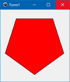
A polygon is drawn by the Polygon method of the canvas. The polygon is defined by an array of points (TPoint) which are connected by straight lines drawn with the current Pen, and the inner area is filled by the current Brush. The polygon is closed automatically, i.e. the last array point does not necessarily need to coincide with the first point (although there are cases where this is required -- see below).
Example: Pentagon
procedure TForm1.FormPaint(Sender: TObject);
var
  P: Array[0..4] of TPoint;
  i: Integer;
  phi: Double;

begin
  for i := 0 to 4 do
  begin
    phi := 2.0 * pi / 5 * i + pi * 0.5;;
    P[i].X := round(100 * cos(phi) + 110);
    P[i].Y := round(100 * sin(phi) + 110);
  end;
  Canvas.Brush.Color := clRed;
  Canvas.Polygon(P);
end;
Self-overlapping polygons
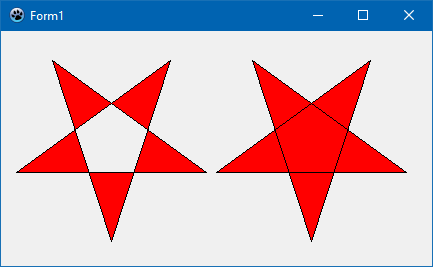
Here is a modification of the polygon example: Let's rearrange the polygon points so that the first point is connected to the 3rd initial point, the 3rd point is connected to the 5th point, the 5th point to the 2nd point and the 2nd point to to 4th point. This is a self-overlapping polygon and results in a star-shape. However, owing to the overlapping, different effects can be obtained which depend on the optional Winding parameter of the Polygon() method. When Winding is False an area is filled by the "even-odd rule" (https://en.wikipedia.org/wiki/Even%E2%80%93odd_rule), otherwise by the "non-zero winding rule" (https://en.wikipedia.org/wiki/Nonzero-rule). The following code example compares both cases:
procedure TForm1.FormPaint(Sender: TObject);
var
  P: Array[0..4] of TPoint;
  P1, P2: Array[0..4] of TPoint;
  i: Integer;
  phi: Double;
begin
  for i := 0 to 4 do
  begin
    phi := 2.0 * pi / 5 * i + pi * 0.5;;
    P[i].X := round(100 * cos(phi) + 110);
    P[i].Y := round(100 * sin(phi) + 110);
  end;
  P1[0] := P[0];
  P1[1] := P[2];
  P1[2] := P[4];
  P1[3] := P[1];
  P1[4] := P[3];
  for i:= 0 to 4 do P2[i] := Point(P1[i].X + 200, P1[i].Y);  // offset polygon
  Canvas.Brush.Color := clRed;
  Canvas.Polygon(P1, false);  // false --> Even-odd rule
  Canvas.Polygon(P2, true);   // true ---> Non-zero winding rule
end;
Polygon with a hole
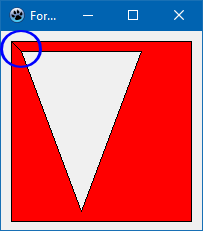
Suppose you want to draw the shape of a country with a large lake inside from both of which you have some boundary points. Basically the Polygon() method of the LCL canvas is ready for this task. However, you need to consider several important points:
- You must prepare the array of polygon vertices such that each polygon is closed (i.e. last point = first point), and that both first and last polygon points are immediately adjacent in the array.
- The order of the inner and outer polygon points in the array does not matter.
- Make sure that both polygons have opposite orientations, i.e. if the outer polygon has its vertices in clockwise order, then the inner polygon must have the points in counter-clockwise order.
Example:
const
  P: array of [0..8] of TPoint = (
    // outer polygon: a rectangle
    (X: 10; Y: 10),   // <--- first point of the rectangle
    (X:190; Y: 10),
    (X:190; Y:190),   //      (clockwise orientation)
    (X: 10; Y:190),
    (X: 10; Y: 10),   // <--- last point of the rectangle = first point

    // inner polygon: a triangle
    (X: 20; Y: 20),   // <--- first point of the triangle
    (X: 40; Y:180),   //      ( counter-clockwise orientation)
    (X: 60; Y: 20),
    (X: 20; Y: 20)    // <--- last point of the triangle = first point
  );

procedure TForm1.FormPaint(Sender: TObject);
begin
  Canvas.Brush.Color := clRed;
  Canvas.Polygon(Pts);
end;
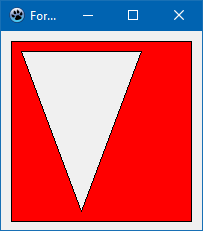
You may notice that there is a line connecting the starting point of the inner triangle back to the starting point of the outer rectangle (marked by a blue circle in the screenshot). This is because the Polygon() method closes the entire polygon, i.e. it connects the very first with the very last array point. You can avoid this by drawing the polygon and the border separately. To draw the fill the Pen.Style should be set to psClear to hide the outline. The PolyLine() method can be used to draw the border; this method needs arguments for the starting point index and also a count of the array points to be drawn.
procedure TForm1.FormPaint(Sender: TObject);
begin
  Canvas.Brush.Color := clRed;
  Canvas.Pen.Style := psClear;
  Canvas.Polygon(Pts);

  Canvas.Pen.Style := psSolid;
  Canvas.Pen.Color := clBlack;
  Canvas.Polyline(Pts, 0, 5);  // rectangle starts at index 0 and consists of 5 array elements
  Canvas.Polyline(Pts, 5, 4);  // triangle starts at index 5 and consists of 4 array elements
end;
Polygon with several holes
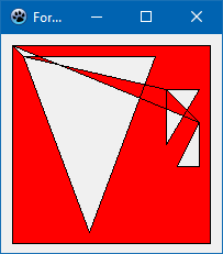
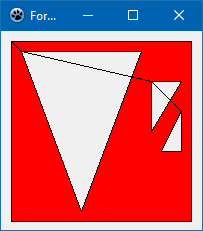
Applying the rules for the single hole in a polygon, we extend the example from the previous section by adding two more triangles inside the outer rectangle. These triangles have the same orientation as the first triangle, opposite to the outer rectangle, and thus should be considered to be holes.
const
  Pts: array[0..16] of TPoint = (
    // outer polygon: a rectangle
    (X: 10; Y: 10),    // clockwise
    (X:190; Y: 10),
    (X:190; Y:190),
    (X: 10; Y:190),
    (X: 10; Y: 10),

    // inner polygon: a triangle
    (X:  20; Y: 20),   // counter-clockwise
    (X:  80; Y:180),
    (X: 140; Y: 20),
    (X:  20; Y: 20),

    // 2nd inner triangle
    (X: 150; Y: 50),   // counter-clockwise
    (X: 150; Y:100),
    (X: 180; Y: 50),
    (X: 150; Y: 50),

    // 3rd inner triangle
    (X: 180; Y: 80),  // counter-clockwise
    (X: 160; Y:120),
    (X: 180; Y:120),
    (X: 180; Y: 80)
  );
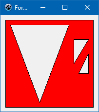
Rendering this by a simple Polygon() fill is disappointing because there are new additional areas with are not expected. The reason is that this model does not return to the starting point correctly. The trick is to add two further points (one per shape). These are added to the above single-hole-in-polygon case: the first additional point duplicates the first point of the 2nd inner triangle, and the second additional point duplicates the first point of the 1st inner triangle. By so doing, the polygon is closed along the imaginary path the holes were connected by initially, and no additional areas are introduced:
const
  Pts: array[0..18] of TPoint = (
    // outer polygon: a rectangle
    (X: 10; Y: 10),    // clockwise
    (X:190; Y: 10),
    (X:190; Y:190),
    (X: 10; Y:190),
    (X: 10; Y: 10),

    // 1st inner triangle
    (X:  20; Y: 20),   // counter-clockwise --> hole
    (X:  80; Y:180),
    (X: 140; Y: 20),
    (X:  20; Y: 20),

    // 2nd inner triangle
    (X: 150; Y: 50),   // counter-clockwise --> hole
    (X: 150; Y:100),
    (X: 180; Y: 50),
    (X: 150; Y: 50),

    // 3rd inner triangle
    (X: 180; Y: 80),  // counter-clockwise --> hole
    (X: 160; Y:120),
    (X: 180; Y:120),
    (X: 180; Y: 80),

    (X: 150; Y: 50),  // duplicates 1st point of 2nd inner triangle
    (X:  20; Y: 20)   // duplicates 1st point of 1st inner triangle
  );
The last image at the right is drawn again with separate Polygon() and PolyLine() calls.
Drawing Text
Text painting methods
There are two basic methods how to draw text by means of Canvas methods:
TCanvas.TextOut(x, y: Integer; const AText: String)
This is the simplest way to draw the given text. Its top/left corner is at the position x/y.
TCanvas.TextRect(R: TRect; x, y: Integer; const AText: String; const Style: TTextStyle)
The (optional) TTextStyle parameter allows to apply various options to control the text output:
- Alignment: TAlignment = (taLeftJustify, taRightJustify, taCenter): horizontal alignment of the text within the rectangle given as parameter R. When Alignment is taLeftJustify the text begins at <x> (measured relative to the canvas); otherwise the text is centered or right-aligned in the rectangle (x is ignored now).
- Layout: TTextLayout = (tlTop, tlCenter, tlBottom): Analogous to Alignment, but for the vertical direction.
- SingleLine: Boolean: If WordBreak is false then process #13, #10 as standard chars and perform no line breaking.
- Wordbreak: boolean: If line of text is too long to fit between left and right boundaries, it is attempted to break the text between words into multiple lines. See also EndEllipsis.
- EndEllipsis: Boolean: If line of text is too long to fit between left and right boundaries, the text is truncated the text and an ellipsis ('...') is added. If Wordbreak is set as well, Workbreak will dominate.
- Clipping: boolean: Clips the text to the passed rectangle.
- ExpandTabs: boolean: Replaces #9 by appropriate amount of spaces (default is usually 8).
- ShowPrefix: boolean: Processes the first single '&' per line as an underscore and draws '&&' as '&'.
- Opaque: boolean: Fills background with the current Brush
- SystemFont: Boolean: Uses the system font instead of Canvas Font
- RightToLeft: Boolean: For RightToLeft text reading (Text Direction)
Alternatively there is also the Windows-like DrawText function. Although it follows Windows syntax the procedure in unit LCLIntf is cross-platform.
function DrawText(DC: HDC; Str: PChar; Count: Integer; var Rect: TRect; Flags: Cardinal): Integer
- DC: Handle of the canvas, e.g. Paintbox1.Canvas.Handle
- Str: Text to be written, cast to PChar
- Count: Number of bytes to be sent to the DrawText function, use Length(Str)
- Rect: Rectangle within the output should occur. Returns the smallest rectangle occupied by the text.
- Flags: Can contain a long list of values combined by logical "or" representing options to control the output. Among them DT_LEFT, DT_CENTER, DT_RIGHT for horizontal, DT_TOP, DT_VCENTER, DT_BOTTOM for vertical alignment, or DT_SINGLELINE, DT_WORDBREAK, DT_END_ELLIPSIS to control multiline behaviour. An important option is DT_CALCRECT which suppresses painting but returns the size needed for the text output in the TRect parameter. See https://learn.microsoft.com/en-us/windows/win32/api/winuser/nf-winuser-drawtext for a complete list.
Using the default GUI font
This can be done with the following simple code:
SelectObject(Canvas.Handle, GetStockObject(DEFAULT_GUI_FONT));
or:
Canvas.Font.Name := 'default';
Drawing text to an exactly fitting width
Use the DrawText routine, first with DT_CALCRECT and then without it.
// First calculate the text size then draw it
TextBox := Rect(0, currentPos.Y, Width, High(Integer));
DrawText(ACanvas.Handle, PChar(Text), Length(Text),
  TextBox, DT_WORDBREAK or DT_INTERNAL or DT_CALCRECT);

DrawText(ACanvas.Handle, PChar(Text), Length(Text),
  TextBox, DT_WORDBREAK or DT_INTERNAL);
Drawing text with sharp edges (non antialiased)
Some widgetsets support this via
Canvas.Font.Quality := fqNonAntialiased;
Some widgetsets like the gtk2 do not support this and always paint antialiased. Here is a simple procedure to draw text with sharp edges under gtk2. It does not consider all cases, but it should give an idea:
procedure PaintAliased(Canvas: TCanvas; x, y: integer; const TheText: string);
var
  w, h, dx, dy: Integer;
  IntfImg:      TLazIntfImage;
  Img:          TBitmap;
  col:          TFPColor;
  FontColor, c: TColor;
begin
  w := 0;
  h := 0;
  Canvas.GetTextSize(TheText, w, h);
  if (w <= 0) or (h <= 0) then exit;
  Img := TBitmap.Create;
  IntfImg := nil;
  try
    // paint text to a bitmap
    Img.Masked := true;
    Img.SetSize(w,h);
    Img.Canvas.Brush.Style := bsSolid;
    Img.Canvas.Brush.Color := clWhite;
    Img.Canvas.FillRect(0, 0, w, h);
    Img.Canvas.Font := Canvas.Font;
    Img.Canvas.TextOut(0, 0, TheText);
    // get memory image
    IntfImg := Img.CreateIntfImage;
    // replace gray pixels
    FontColor := ColorToRGB(Canvas.Font.Color);
    for dy := 0 to h - 1 do begin
      for dx := 0 to w - 1 do begin
        col := IntfImg.Colors[dx, dy];
        c := FPColorToTColor(col);
        if c <> FontColor then
          IntfImg.Colors[dx, dy] := colTransparent;
      end;
    end;
    // create bitmap
    Img.LoadFromIntfImage(IntfImg);
    // paint
    Canvas.Draw(x, y, Img);
  finally
    IntfImg.Free;
    Img.Free;
  end;
end;
Lavorare con TBitmap e altri discendenti di TGraphic
L'oggetto TBitmap gestisce una bitmap dove è possibile disegnare prima di riprodurre sullo schermo. Creando una bitmap bisogna specificarne altezza e larghezza, altrimenti essa rimarrà vuota nulla verrà riprodotto. In generale i discendenti di TRasterImage forniscono funzionalità simili, ma le prestazioni possono essere diverse per le operazioni di I/O su disco.
Caricare/Salvare un'immagine da/su disco
Per caricare un'immagine da disco usare TGraphic.LoadFromFile e per salvarla in un altro file usare TGraphic.SaveToFile. Tra le classi discendenti da TGraphic usare la classe appropriata per il formato di file. Vedere Developing_with_Graphics#Image_formats per una lista delle classi disponibili per i vari formati.
var
  MyBitmap: TBitmap;
begin
  MyBitmap := TBitmap.Create;
  try
    // Load from disk
    MyBitmap.LoadFromFile(MyEdit.Text);

    // Here you can use MyBitmap.Canvas to read/write to/from the image

    // Write back to another disk file
    MyBitmap.SaveToFile(MyEdit2.Text);
  finally
    MyBitmap.Free;
  end;
end;
Per altri formati la procedura è completamente identica, usando la classe appropriata. Ad esempio per immagini PNG:
var
  MyPNG: TPortableNetworkGraphic;
begin
  MyPNG := TPortableNetworkGraphic.Create;
  try
    // Load from disk
    MyPNG.LoadFromFile(MyEdit.Text);

    // Here you can use MyPNG.Canvas to read/write to/from the image

    // Write back to another disk file
    MyPNG.SaveToFile(MyEdit2.Text);
  finally
    MyPNG.Free;
  end;
end;
Se il formato dell'immagine non è noto, usare TPicture che determinerà il formato in base all'estensione del file. Si noti che TPicture non supporta tutti i formati supportati da Lazarus: alla versione 0.9.31 TPicture supporta BMP, PNG, JPEG, Pixmap and PNM mentre Lazarus supporta anche ICNS e altri formati:
var
  MyPicture: TPicture;
begin
  MyPicture := TPicture.Create;
  try
    // Load from disk
    MyPicture.LoadFromFile(MyEdit.Text);

    // Here you can use MyPicture.Graphic.Canvas to read/write to/from the image

    // Write back to another disk file
    MyPicture.SaveToFile(MyEdit2.Text);
  finally
    MyPicture.Free;
  end;
end;
File format addizionali per TImage
Si può avere supporto per formati addizionali aggiungendo le unità fcl-image fpread* e/o fpwrite* nella dichiarazione uses. In tal modo si aggiunge il supporto TIFF per TImage
Accesso diretto ai pixel
Per accedere direttamente ai pixel di un bitmap si può usare sia una libreria esterna, come BGRABitmap, LazRGBGraphics eGraphics32, oppure usare la classe nativa di Lazarus TLazIntfImage. Per un confronto dei vari metodi vedere fast direct pixel access.
On some Lazarus widgetsets (notably LCL-Gtk2), the bitmap data is not stored in memory location which can be accessed by the application and in general the LCL native interfaces draw only through native Canvas routines, so each SetPixel / GetPixel operation involves a slow call to the native Canvas API. In LCL-CustomDrawn this is not the case since the bitmap is locally stored for all backends and SetPixel / GetPixel is fast. For obtaining a solution which works in all widgetsets one should use TLazIntfImage. As Lazarus is meant to be platform independent and work in gtk2, the TBitmap class does not provide a property like Scanline. There is a GetDataLineStart function, equivalent to Scanline, but only available for memory images like TLazIntfImage which internally uses TRawImage.
To sum it up, with the standard TBitmap, you can only change pixels indirectly, by using TCanvas.Pixels. Calling a native API to draw / read an individual pixel is course slower than direct pixel access, notably so in LCL-gtk2 and LCL-Carbon.
Note: what about this bug report: http://bugs.freepascal.org/view.php?id=1958 with comment: I tested with trunk on Qt. ScanLine is here and works. It has to be used like this: Bitmap.BeginUpdate; //do some ScanLine job Bitmap.EndUpdate; PLEASE REVISE THIS SECTION!
Drawing color transparent bitmaps
A new feature, implemented on Lazarus 0.9.11, is color transparent bitmaps. Bitmap files (*.BMP) cannot store any information about transparency, but they can work as they had if you select a color on them to represent the transparent area. This is a common trick used on Win32 applications.
The following example loads a bitmap from a Windows resource, selects a color to be transparent (clFuchsia) and then draws it to a canvas.
procedure MyForm.MyButtonOnClick(Sender: TObject);
var
  buffer: THandle;
  bmp: TBitmap;
  memstream: TMemoryStream;
begin
  bmp := TBitmap.Create;

  buffer := Windows.LoadBitmap(hInstance, MAKEINTRESOURCE(ResourceID));

  if (buffer = 0) then exit; // Error loading the bitmap

  bmp.Handle := buffer;
  memstream := TMemoryStream.create;
  try
    bmp.SaveToStream(memstream);
    memstream.position := 0;
    bmp.LoadFromStream(memstream);
  finally
    memstream.free;
  end;

  bmp.Transparent := True;
  bmp.TransparentColor := clFuchsia;

  MyCanvas.Draw(0, 0, bmp);

  bmp.Free; // Release allocated resource
end;
Notice the memory operations performed with the TMemoryStream. They are necessary to ensure the correct loading of the image.
Taking a screenshot of the screen
Since Lazarus 0.9.16 you can use LCL to take screenshots of the screen in a cross-platform way. The following example code does it:
uses Graphics, LCLIntf, LCLType;
  ...
var
  MyBitmap: TBitmap;
  ScreenDC: HDC;
begin
  MyBitmap := TBitmap.Create;
  ScreenDC := GetDC(0);
  MyBitmap.LoadFromDevice(ScreenDC);
  ReleaseDC(0,ScreenDC);
  ...
Working with TLazIntfImage, TRawImage and TLazCanvas
TLazIntfImage is a non-native equivalent of TRasterImage (more commonly utilized in the form of it's descendent TBitmap). The first thing to be aware about this class is that unlike TBitmap it will not automatically allocate a memory area for the bitmap, one should first initialize a memory area and then give it to the TLazIntfImage. Right after creating a TLazIntfImage one should either connect it to a TRawImage or load it from a TBitmap.
TRawImage is of the type object and therefore does not need to be created nor freed. It can either allocate the image memory itself when one calls TRawImage.CreateData or one can pass a memory block allocated for examply by a 3rd party library such as the Windows API of the Cocoa Framework from Mac OS X and pass the information of the image in TRawImage.Description, TRawImage.Data and TRawImage.DataSize. Instead of attaching it to a RawImage one could also load it from a TBitmap which will copy the data from the TBitmap and won't be syncronized with it afterwards. The TLazCanvas cannot exist alone and must always be attached to a TLazIntfImage.
The example below shows how to choose a format for the data and ask the TRawImage to create it for us and then we attach it to a TLazIntfImage and then attach a TLazCanvas to it:
uses graphtype, intfgraphics, lazcanvas;

var
  AImage: TLazIntfImage;
  ACanvas: TLazCanvas;
  lRawImage: TRawImage;
begin
    lRawImage.Init;
    lRawImage.Description.Init_BPP32_A8R8G8B8_BIO_TTB(AWidth, AHeight);
    lRawImage.CreateData(True);
    AImage := TLazIntfImage.Create(0,0);
    AImage.SetRawImage(lRawImage);
    ACanvas := TLazCanvas.Create(AImage);
Initializing a TLazIntfImage
One cannot simply create an instance of TLazIntfImage and start using it. It needs to add a storage to it. There are 3 ways to do this:
1. Attach it to a TRawImage
2. Load it from a TBitmap. Note that it will copy the memory of the TBitmap so it won't remain connected to it.
   SrcIntfImg:=TLazIntfImage.Create(0,0);
   SrcIntfImg.LoadFromBitmap(ABitmap.Handle,ABitmap.MaskHandle);
3. Load it from a raw image description, like this:
   IntfImg := TLazIntfImage.Create(0,0);
   IntfImg.DataDescription:=GetDescriptionFromDevice(0);
   IntfImg.SetSize(10,10);
The 0 device in GetDescriptionFromDevice(0) uses the current screen format.
TLazIntfImage.LoadFromFile
Here is an example how to load an image directly into a TLazIntfImage. It initializes the TLazIntfImage to a 32bit RGBA format. Keep in mind that this is probably not the native format of your screen.
uses LazLogger, Graphics, IntfGraphics, GraphType;
procedure TForm1.FormCreate(Sender: TObject);
var
  AImage: TLazIntfImage;
  lRawImage: TRawImage;
begin
  // create a TLazIntfImage with 32 bits per pixel, alpha 8bit, red 8 bit, green 8bit, blue 8bit,
  // Bits In Order: bit 0 is pixel 0, Top To Bottom: line 0 is top
  lRawImage.Init;
  lRawImage.Description.Init_BPP32_A8R8G8B8_BIO_TTB(0,0);
  lRawImage.CreateData(false);
  AImage := TLazIntfImage.Create(0,0);
  try
    AImage.SetRawImage(lRawImage);
    // Load an image from disk.
    // It uses the file extension to select the right registered image reader.
    // The AImage will be resized to the width, height of the loaded image.
    AImage.LoadFromFile('lazarus/examples/openglcontrol/data/texture1.png');
    debugln(['TForm1.FormCreate ',AImage.Width,' ',AImage.Height]);
  finally
    AImage.Free;
  end;
end;
Loading a TLazIntfImage into a TImage
The pixel data of a TImage is the TImage.Picture property, which is of type TPicture. TPicture is a multi format container containing one of several common image formats like Bitmap, Icon, Jpeg or PNG . Usually you will use the TPicture.Bitmap to load a TLazIntfImage:
Image1.Picture.Bitmap.LoadFromIntfImage(IntfImg);Notes:
- To load a transparent TLazIntfImage you have to set the Image1.Transparent to true.
- TImage uses the screen format. If the TLazIntfImage has a different format then the pixels will be converted. Hint: You can use IntfImg.DataDescription:=GetDescriptionFromDevice(0); to initialize the TLazIntfImage with the screen format.
Fading example
A fading example with TLazIntfImage
{ This code has been taken from the $LazarusPath/examples/lazintfimage/fadein1.lpi project. }
uses LCLType, // HBitmap type
     IntfGraphics, // TLazIntfImage type
     fpImage; // TFPColor type
...
 procedure TForm1.FadeIn(ABitMap: TBitMap);
 var
   SrcIntfImg, TempIntfImg: TLazIntfImage;
   ImgHandle,ImgMaskHandle: HBitmap;
   FadeStep: Integer;
   px, py: Integer;
   CurColor: TFPColor;
   TempBitmap: TBitmap;
 begin
   SrcIntfImg:=TLazIntfImage.Create(0,0);
   SrcIntfImg.LoadFromBitmap(ABitmap.Handle,ABitmap.MaskHandle);
   TempIntfImg:=TLazIntfImage.Create(0,0);
   TempIntfImg.LoadFromBitmap(ABitmap.Handle,ABitmap.MaskHandle);
   TempBitmap:=TBitmap.Create;
   for FadeStep:=1 to 32 do begin
     for py:=0 to SrcIntfImg.Height-1 do begin
       for px:=0 to SrcIntfImg.Width-1 do begin
         CurColor:=SrcIntfImg.Colors[px,py];
         CurColor.Red:=(CurColor.Red*FadeStep) shr 5;
         CurColor.Green:=(CurColor.Green*FadeStep) shr 5;
         CurColor.Blue:=(CurColor.Blue*FadeStep) shr 5;
         TempIntfImg.Colors[px,py]:=CurColor;
       end;
     end;
     TempIntfImg.CreateBitmaps(ImgHandle,ImgMaskHandle,false);
     TempBitmap.Handle:=ImgHandle;
     TempBitmap.MaskHandle:=ImgMaskHandle;
     Canvas.Draw(0,0,TempBitmap);
   end;
   SrcIntfImg.Free;
   TempIntfImg.Free;
   TempBitmap.Free;
 end;
Image format specific example
If you know that the TBitmap is using blue 8bit, green 8bit, red 8bit you can directly access the bytes, which is somewhat faster:
uses LCLType, // HBitmap type
     IntfGraphics, // TLazIntfImage type
     fpImage; // TFPColor type
...
type
  TRGBTripleArray = array[0..32767] of TRGBTriple;
  PRGBTripleArray = ^TRGBTripleArray;

procedure TForm1.FadeIn2(aBitMap: TBitMap);
 var
   IntfImg1, IntfImg2: TLazIntfImage;
   ImgHandle,ImgMaskHandle: HBitmap;
   FadeStep: Integer;
   px, py: Integer;
   CurColor: TFPColor;
   TempBitmap: TBitmap;
   Row1, Row2: PRGBTripleArray;
 begin
   IntfImg1:=TLazIntfImage.Create(0,0);
   IntfImg1.LoadFromBitmap(aBitmap.Handle,aBitmap.MaskHandle);

   IntfImg2:=TLazIntfImage.Create(0,0);
   IntfImg2.LoadFromBitmap(aBitmap.Handle,aBitmap.MaskHandle);

   TempBitmap:=TBitmap.Create;

   //with Scanline-like
   for FadeStep:=1 to 32 do begin
     for py:=0 to IntfImg1.Height-1 do begin
       Row1 := IntfImg1.GetDataLineStart(py); //like Delphi TBitMap.ScanLine
       Row2 := IntfImg2.GetDataLineStart(py); //like Delphi TBitMap.ScanLine
       for px:=0 to IntfImg1.Width-1 do begin
         Row2^[px].rgbtRed:= (FadeStep * Row1^[px].rgbtRed) shr 5;
         Row2^[px].rgbtGreen := (FadeStep * Row1^[px].rgbtGreen) shr 5; // Fading
         Row2^[px].rgbtBlue := (FadeStep * Row1^[px].rgbtBlue) shr 5;
       end;
     end;
     IntfImg2.CreateBitmaps(ImgHandle,ImgMaskHandle,false);

     TempBitmap.Handle:=ImgHandle;
     TempBitmap.MaskHandle:=ImgMaskHandle;
     Canvas.Draw(0,0,TempBitmap);
   end;

   IntfImg1.Free;
   IntfImg2.Free;
   TempBitmap.Free;
 end;
Conversion between TLazIntfImage and TBitmap
Since Lazarus has no TBitmap.ScanLines property, the best way to access the pixels of an image in a fast way for both reading and writing is by using TLazIntfImage. The TBitmap can be converted to a TLazIntfImage by using TBitmap.CreateIntfImage() and after modifying the pixels it can be converted back to a TBitmap by using TBitmap.LoadFromIntfImage(); Here's the sample on how to create TLazIntfImage from TBitmap, modify it and then go back to the TBitmap.
uses
  ...GraphType, IntfGraphics, LCLType, LCLProc,  LCLIntf ...

procedure TForm1.Button4Click(Sender: TObject);
var
  b: TBitmap;
  t: TLazIntfImage;
begin
  b := TBitmap.Create;
  try
    b.LoadFromFile('test.bmp');
    t := b.CreateIntfImage;

    // Read and/or write to the pixels
    t.Colors[10,20] := colGreen;

    b.LoadFromIntfImage(t);
  finally
    t.Free;
    b.Free;
  end;
end;
Using the non-native StretchDraw from LazCanvas
Just like TCanvas.StretchDraw there is TLazCanvas.StretchDraw but you need to specify the interpolation which you desire to use. The interpolation which provides a Windows-like StretchDraw with a very sharp result (the opposite of anti-aliased) can be added with: TLazCanvas.Interpolation := TFPSharpInterpolation.Create;
There are other interpolations available in the unit fpcanvas.
uses intfgraphics, lazcanvas;

procedure TForm1.StretchDrawBitmapToBitmap(SourceBitmap, DestBitmap: TBitmap; DestWidth, DestHeight: integer);
var
  DestIntfImage, SourceIntfImage: TLazIntfImage;
  DestCanvas: TLazCanvas;
begin
  // Prepare the destination

  DestIntfImage := TLazIntfImage.Create(0, 0);
  DestIntfImage.LoadFromBitmap(DestBitmap.Handle, 0);

  DestCanvas := TLazCanvas.Create(DestIntfImage);

  //Prepare the source
  SourceIntfImage := TLazIntfImage.Create(0, 0);
  SourceIntfImage.LoadFromBitmap(SourceBitmap.Handle, 0);

  // Execute the stretch draw via TFPSharpInterpolation
  DestCanvas.Interpolation := TFPSharpInterpolation.Create;
  DestCanvas.StretchDraw(0, 0, DestWidth, DestHeight, SourceIntfImage);

  // Reload the image into the TBitmap
  DestBitmap.LoadFromIntfImage(DestIntfImage);

  SourceIntfImage.Free;
  DestCanvas.Interpolation.Free;
  DestCanvas.Free;
  DestIntfImage.Free;
end;

procedure TForm1.FormPaint(Sender: TObject);
var
  Bmp, DestBitmap: TBitmap;
begin
  // Prepare the destination
  DestBitmap := TBitmap.Create;
  DestBitmap.Width := 100;
  DestBitmap.Height := 100;

  Bmp := TBitmap.Create;
  Bmp.Width := 10;
  Bmp.Height := 10;
  Bmp.Canvas.Pen.Color := clYellow;
  Bmp.Canvas.Brush.Color := clYellow;
  Bmp.Canvas.Rectangle(0, 0, 10, 10);
  StretchDrawBitmapToBitmap(Bmp, DestBitmap, 100, 100);
  Canvas.Draw(0, 0, Bmp);
  Canvas.Draw(100, 100, DestBitmap);
end;
Motion Graphics - How to Avoid flickering
Many programs draw their output to the GUI as 2D graphics. If those graphics need to change quickly you will soon face a problem: quickly changing graphics often flicker on the screen. This happens when users sometimes see the whole images and sometimes only when it is partially drawn. It occurs because the painting process requires time.
How can you avoid the flickering and get the best drawing speed? Of course you could work with hardware acceleration using OpenGL, but this approach is quite heavy for small programs or old computers.
Another solution is drawing to a TCanvas. If you need help with OpenGL, take a look at the example that comes with Lazarus. You can also use A.J. Venter's gamepack, which provides a double-buffered canvas and a sprite component.
A brief and very helpful article on avoiding flicker can be found at http://delphi.about.com/library/bluc/text/uc052102g.htm. Although written for Delphi, the techniques work well with Lazarus.
Now we will examine the options we have for drawing to a Canvas:
- Draw to a TImage
- Draw on the OnPaint event of the form, a TPaintBox or another control
- Create a custom control which draws itself
- Using A.J. Venter's gamepack
Draw to a TImage
A TImage consists of 2 parts: A TGraphic, usually a TBitmap, holding the persistent picture and the visual area, which is repainted on every OnPaint. Resizing the TImage does not resize the bitmap. The graphic (or bitmap) is accessible via Image1.Picture.Graphic (or Image1.Picture.Bitmap). The canvas is Image1.Picture.Bitmap.Canvas. The canvas of the visual area of a TImage is only accessible during Image1.OnPaint via Image1.Canvas.
Important: Never use the OnPaint of the Image1 event to draw to the graphic/bitmap of a TImage. The graphic of a TImage is buffered so all you need to do is draw to it from anywhere and the change is there forever. However, if you are constantly redrawing, the image will flicker. In this case you can try the other options. Drawing to a TImage is considered slower then the other approaches.
Resizing the bitmap of a TImage
with Image1.Picture.Bitmap do begin
  Width:=100;
  Height:=120;
end;
Same in one step:
with Image1.Picture.Bitmap do begin
  SetSize(100, 120);
end;
Painting on the bitmap of a TImage
with Image1.Picture.Bitmap.Canvas do begin
  // fill the entire bitmap with red
  Brush.Color := clRed;
  FillRect(0, 0, Width, Height);
end;Another example:
procedure TForm1.BitBtn1Click(Sender: TObject);
var
  x, y: Integer;
begin
  // Draws the backgroung
  MyImage.Canvas.Pen.Color := clWhite;
  MyImage.Canvas.Rectangle(0, 0, Image.Width, Image.Height);

  // Draws squares
  MyImage.Canvas.Pen.Color := clBlack;
  for x := 1 to 8 do
    for y := 1 to 8 do
      MyImage.Canvas.Rectangle(Round((x - 1) * Image.Width / 8), Round((y - 1) * Image.Height / 8),
        Round(x * Image.Width / 8), Round(y * Image.Height / 8));
end;
Painting on the volatile visual area of the TImage
You can only paint on this area during OnPaint. OnPaint is eventually called automatically by the LCL when the area was invalidated. You can invalidate the area manually with Image1.Invalidate. This will not immediately call OnPaint and you can call Invalidate as many times as you want.
procedure TForm.Image1Paint(Sender: TObject);
begin
  // paint a line
  Canvas.Pen.Color := clRed;
  Canvas.Line(0, 0, Width, Height);
end;
Draw on the OnPaint event
In this case all the drawing has to be done on the OnPaint event of the form, or of another control. The drawing isn't buffered like in the TImage, and it needs to be fully redrawn in each call of the OnPaint event handler.
procedure TForm.Form1Paint(Sender: TObject);
begin
  // paint a line
  Canvas.Pen.Color := clRed;
  Canvas.Line(0, 0, Width, Height);
end;
Create a custom control which draws itself
Creating a custom control has the advantage of structuring your code and you can reuse the control. This approach is very fast, but it can still generate flickering if you don't draw to a TBitmap first and then draw to the canvas. On this case there is no need to use the OnPaint event of the control.
Here is an example custom control:
uses
  Classes, SysUtils, Controls, Graphics, LCLType;

type
  TMyDrawingControl = class(TCustomControl)
  public
    procedure EraseBackground(DC: HDC); override;
    procedure Paint; override;
  end;

implementation

procedure TMyDrawingControl.EraseBackground(DC: HDC);
begin
  // Uncomment this to enable default background erasing
  //inherited EraseBackground(DC);
end;

procedure TMyDrawingControl.Paint;
var
  x, y: Integer;
  Bitmap: TBitmap;
begin
  Bitmap := TBitmap.Create;
  try
    // Initializes the Bitmap Size
    Bitmap.Height := Height;
    Bitmap.Width := Width;

    // Draws the background
    Bitmap.Canvas.Pen.Color := clWhite;
    Bitmap.Canvas.Rectangle(0, 0, Width, Height);

    // Draws squares
    Bitmap.Canvas.Pen.Color := clBlack;
    for x := 1 to 8 do
      for y := 1 to 8 do
        Bitmap.Canvas.Rectangle(Round((x - 1) * Width / 8), Round((y - 1) * Height / 8),
          Round(x * Width / 8), Round(y * Height / 8));

    Canvas.Draw(0, 0, Bitmap);
  finally
    Bitmap.Free;
  end;

  inherited Paint;
end;
and how we create it on the form:
procedure TMyForm.FormCreate(Sender: TObject);
begin
  MyDrawingControl := TMyDrawingControl.Create(Self);
  MyDrawingControl.Height := 400;
  MyDrawingControl.Width := 500;
  MyDrawingControl.Top := 0;
  MyDrawingControl.Left := 0;
  MyDrawingControl.Parent := Self;
  MyDrawingControl.DoubleBuffered := True;
end;
It is destroyed automatically, because we use Self as owner.
Setting Top and Left to zero is not necessary, since this is the standard position, but is done so to reinforce where the control will be put.
"MyDrawingControl.Parent := Self;" is very important and you won't see your control if you don't do so.
"MyDrawingControl.DoubleBuffered := True;" is required to avoid flickering on Windows. It has no effect on gtk.
Image formats
Here is a table with the correct class to use for each image format.
| Format | Image class | Unit |
|---|---|---|
| Cursor (cur) | TCursor | Graphics |
| Bitmap (bmp) | TBitmap | Graphics |
| Windows icon (ico) | TIcon | Graphics |
| Mac OS X icon (icns) | TicnsIcon | Graphics |
| Pixmap (xpm) | TPixmap | Graphics |
| Portable Network Graphic (png) | TPortableNetworkGraphic | Graphics |
| JPEG (jpg, jpeg) | TJpegImage | Graphics |
| PNM (pnm) | TPortableAnyMapGraphic | Graphics |
| Tiff (tif, tiff) | TTiffImage | Graphics |
See also the list of fcl-image supported formats.
Converting formats
Sometimes it is necessary to convert one graphic type to another. One of the ways is to convert a graphic to intermediate format, and then convert it to TBitmap. Most of the formats can create an image from TBitmap.
Converting Bitmap to PNG and saving it to a file:
procedure SaveToPng(const bmp: TBitmap; PngFileName: String);
var
  png : TPortableNetworkGraphic;
begin
  png := TPortableNetworkGraphic.Create;
  try
    png.Assign(bmp);
    png.SaveToFile(PngFileName);
  finally
    png.Free;
  end;
end;
Pixel Formats
TColor
The internal pixel format for TColor in the LCL is the XXBBGGRR format, which matches the native Windows format and is opposite to most other libraries, which use AARRGGBB. The XX part is used to identify if the color is a fixed color, which case XX should be 00 or if it is an index to a system color. There is no space reserved for an alpha channel.
To convert from separate RGB channels to TColor use:
RGBToColor(RedVal, GreenVal, BlueVal);To get each channel of a TColor variable use the Red, Green and Blue functions:
RedVal := Red(MyColor);
GreenVal := Green(MyColor);
BlueVal := Blue(MyColor);
TFPColor
TFPColor uses the AARRGGBB format common to most libraries, but it uses 16-bits for the depth of each color channel, totaling 64-bits per pixel, which is unusual. This does not necessarily mean that images will consume that much memory, however. Images created using TRawImage+TLazIntfImage can have any internal storage format and then on drawing operations TFPColor is converted to this internal format.
The unit Graphics provides routines to convert between TColor and TFPColor:
function FPColorToTColorRef(const FPColor: TFPColor): TColorRef;
function FPColorToTColor(const FPColor: TFPColor): TColor;
function TColorToFPColor(const c: TColorRef): TFPColor; overload;
function TColorToFPColor(const c: TColor): TFPColor; overload; // does not work on system color
Drawing with fcl-image
You can draw images which won't be displayed in the screen without the LCL, by just using fcl-image directly. For example a program running on a webserver without X11 could benefit from not having a visual library as a dependency. FPImage (alias fcl-image) is a very generic image and drawing library written completely in Pascal. In fact the LCL uses FPImage too for all the loading and saving from/to files and implements the drawing function through calls to the widgetset (winapi, gtk, carbon, ...). Fcl-image on the other hand also has drawing routines.
For more information, please read the article about fcl-image.
Common OnPaint Error
A common error that causes many false bug reports is to call an Onpaint event for one object from another object. When using the LCL, this may work in GTK2 and Windows but will probably fail with Qt, Carbon and Cocoa. It is not normally necessary to call Invalidate. However, it may sometimes be needed in the Button1Click procedure,
This is bad:
procedure TForm1.Button1Click(Sender: TObject);
begin
  Shape1Paint(Self); // Call Shape1Onpaint event
  Shape1.Invalidate; // Invoke actual painting

  ... more code for Button1 ...
end;
This is good:
procedure TForm1.Button1Click(Sender: TObject);
begin
  ... code for Button1 ...
  Set some condition;
  // Shape1.Invalidate; // May be necessary on some occasions
end;

// Shape1Paint should be attached to the OnPaint event of shape object !
procedure TForm1.Shape1Paint(Sender: TObject);
var
  Myrect: TRect;
begin
  if some condition then
    with Shape1.Canvas do
    begin
      ... lots of stuff ...
    end;
end;
Some useful examples
Example 1: Drawing on loaded JPEG with TImage
Add procedure LoadAndDraw to the public section of your form, and paste next code to implemantation section:
function TForm1.LoadAndDraw(const sFileName: String): Boolean;
var jpg: TPicture;
begin
  bm:=TBitmap.Create;
  jpg:=TPicture.Create;
  jpg.LoadFromFile(sFileName);
  bm.SetSize(jpg.Width, jpg.Height);
  bm.Canvas.Draw(0, 0, jpg.Bitmap);

  image.Picture.Bitmap.SetSize(bm.Width, bm.Height);
  Image.Picture.Bitmap.Canvas.Draw(0, 0, bm);

  Image.Picture.Bitmap.Canvas.Pen.Color:=clRed;
  Image.Picture.Bitmap.Canvas.Line(0,0,140,140);

  jpg.Free;
end;
Example 2: Drawing on controls of Form
1) Create a New project - Application, add to uses section next modules if needed: Types,Controls,Graphics.
2) Place on form Button1, GroupBox1 and RadioGroup1
3) Place on GroupBox1 one more button - Button2
4) Your TForm1.Create should looks like:
procedure TForm1.FormCreate(Sender: TObject);
var
  i: Integer;
begin
  for i:=0 to Self.ControlCount-1 do
      RadioGroup1.Items.AddObject(Controls[i].Name,Controls[i]);

  RadioGroup1.Items.AddObject(Button2.Name,Button2);
end;
5) For RadioGroup1 create handler of OnSelectionChanged event:
procedure TForm1.RadioGroup1SelectionChanged(Sender: TObject);
begin
  Self.Repaint;
end;
6) Add to public section of your form procedure HighlightControl:
 procedure TForm1.HighlightControl(AControl: TControl);
 var
   R: Types.TRect;
   aCC: TControlCanvas;
 begin
   R:=AControl.BoundsRect;
   InflateRect(R,2,2);          // make rect a bit bigger then control
   aCC:=TControlCanvas.Create;
   aCC.Control:=AControl.Parent;
   aCC.Pen.Color:=clGreen;
   aCC.Pen.Width:=5;
   aCC.Pen.Style:=psSolid;
   aCC.Brush.Style:=bsClear;
   aCC.Rectangle(R);
   aCC.free;
 end;
