Difference between revisions of "Lazarus on Raspberry Pi"
| (41 intermediate revisions by 19 users not shown) | |||
| Line 2: | Line 2: | ||
[[File:Lazarus on Raspberry Pi Raspian Wheezy version 2012-10-28.png|thumb|200px|right|alt=Lazarus on Raspbian Wheezy.|Lazarus on Raspbian Wheezy]] | [[File:Lazarus on Raspberry Pi Raspian Wheezy version 2012-10-28.png|thumb|200px|right|alt=Lazarus on Raspbian Wheezy.|Lazarus on Raspbian Wheezy]] | ||
| + | |||
| + | {{Platform only|Raspberry Pi}} | ||
| + | |||
The '''Raspberry Pi''' is a credit-card-sized single-board computer. It has been developed in the UK by the Raspberry Pi Foundation with the intention of stimulating the teaching of basic computer science in schools. Raspberry Pis are also used for multiple other purposes that are as different as media servers, robotics and control engineering. | The '''Raspberry Pi''' is a credit-card-sized single-board computer. It has been developed in the UK by the Raspberry Pi Foundation with the intention of stimulating the teaching of basic computer science in schools. Raspberry Pis are also used for multiple other purposes that are as different as media servers, robotics and control engineering. | ||
| − | The Raspberry Pi Foundation recommends [[Raspbian]] | + | The Raspberry Pi Foundation recommends [[Raspbian]] as standard operating system. Alternative systems running on RPI include RISC OS and various [[Portal:Linux|Linux]] distributions, as well as [[Portal:Android|Android]] and [[Portal:FreeBSD|FreeBSD]]. |
Lazarus runs natively under the Raspbian operating system. | Lazarus runs natively under the Raspbian operating system. | ||
==Installing and compiling Lazarus== | ==Installing and compiling Lazarus== | ||
| + | === Correcting swap file size === | ||
| + | (Info from forum user "Thaddy".) | ||
| + | If you have RPi with memory size less then 4Gb, and you want to use FPCUPdeluxe, you need to adjust the swap file size before installing Lazarus: | ||
| + | |||
| + | * sudo nano /etc/dphys-swapfile | ||
| + | * in the file, find CONF_SWAPSIZE and change the value to 2048 or 1024. | ||
| + | * save and restart. | ||
===Simple installation under Raspbian=== | ===Simple installation under Raspbian=== | ||
| − | + | ==== Modern Raspbian versions ==== | |
| + | |||
| + | On modern versions of Raspbian installation is very easy. It can be performed with the PiPackage manager. You have to select simply "Add / Remove Software" in the global Preferences menu. | ||
| + | |||
| + | <gallery> | ||
| + | Installing FPC on Raspbian Stretch.jpeg|Step 1: Install Free Pascal with PiPackage. | ||
| + | Installing Lazarus on Raspbian Stretch.jpeg|Step 2: Install Lazarus | ||
| + | Running Lazarus from the "Programming" menu on Raspbian Stretch.jpeg|Lazarus is now available in the global "Programming" menu | ||
| + | Lazarus 1 6 on Raspbian Stretch.jpg|A simple session with Lazarus on Raspbian Stretch. | ||
| + | </gallery> | ||
| + | |||
| + | ==== Old Raspbian versions ==== | ||
| + | |||
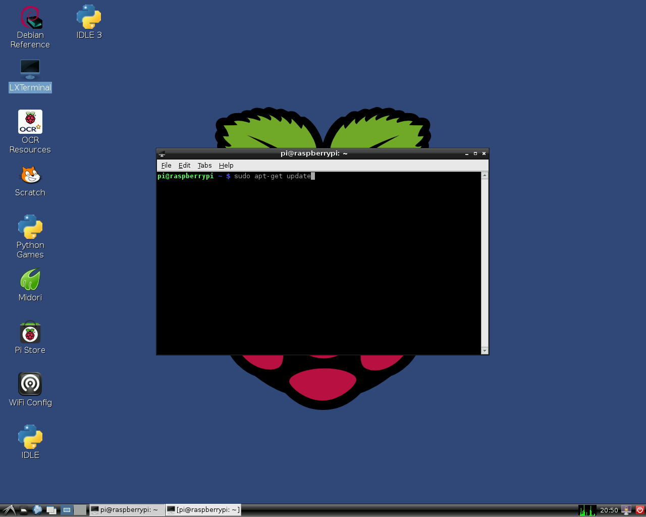
| + | Old versions of Raspbian OS (e.g. Wheezy) don't provide the graphical installer. However, it is easy to install Lazarus and Free Pascal anyway. In order to do this simply open a terminal window and type: | ||
| − | <syntaxhighlight | + | <syntaxhighlight lang="bash"> |
sudo apt-get update | sudo apt-get update | ||
sudo apt-get upgrade | sudo apt-get upgrade | ||
sudo apt-get install fpc | sudo apt-get install fpc | ||
| + | |||
sudo apt-get install lazarus | sudo apt-get install lazarus | ||
</syntaxhighlight> | </syntaxhighlight> | ||
| − | This installs a precompiled version of Lazarus on the Raspberry Pi. Of course, a network connection is required. Installation may take about 30 minutes, but major portions of this process take place automatically. After installation you may instantly start Lazarus from the "Programming" section of the LXDE start menu. | + | Note: if '''sudo apt-get install fpc''' returns unable to find fpc, repeat the '''sudo apt-get update''' |
| + | |||
| + | This installs a precompiled, stable version of FPC and Lazarus on the Raspberry Pi. Of course, a network connection is required. Installation may take about 30 minutes, but major portions of this process take place automatically. After installation you may instantly start Lazarus from the "Programming" section of the LXDE start menu. | ||
<gallery> | <gallery> | ||
| Line 28: | Line 54: | ||
Install Lazarus Rasbian Part3 en.png|Installation 3 | Install Lazarus Rasbian Part3 en.png|Installation 3 | ||
Install Lazarus Rasbian Part4 en.png|Installation 4 | Install Lazarus Rasbian Part4 en.png|Installation 4 | ||
| + | </gallery> | ||
| + | |||
| + | <gallery> | ||
| + | File:Lazarus 0 9 30 4 on RPi 2.png|Lazarus "out of the box" on Raspberry Pi 2 | ||
</gallery> | </gallery> | ||
===Cross compiling for the Raspberry Pi from Windows=== | ===Cross compiling for the Raspberry Pi from Windows=== | ||
| − | 1. | + | 1. Using fpcup |
| − | + | ||
| − | + | One way is to use fpcup to set up a cross compiler; follow these instructions: | |
| + | [[fpcup#Linux_ARM_cross_compiler]] | ||
| + | |||
| + | 2. Using scripts | ||
| − | 1.2 Example | + | Alternatively, for a more manual approach using batch files, you can follow these steps. |
| − | <syntaxhighlight | + | |
| + | 2.1 Prerequisites | ||
| + | FPC 2.7.1 or higher installed with source code | ||
| + | Install the Windows version from the Linaro binutils for linux gnueabihf into %FPCPATH%/bin/win32-armhf-linux [https://launchpad.net/linaro-toolchain-binaries/trunk/2013.10/+download/gcc-linaro-arm-linux-gnueabihf-4.8-2013.10_win32.zip] | ||
| + | |||
| + | 2.2 Example Windows Batch file (adapt paths as needed) | ||
| + | |||
| + | <syntaxhighlight lang="bat"> | ||
set PATH=C:\pp\bin\i386-win32;%PATH%; | set PATH=C:\pp\bin\i386-win32;%PATH%; | ||
set FPCMAKEPATH=C:/pp | set FPCMAKEPATH=C:/pp | ||
| Line 52: | Line 92: | ||
With the resulting ppcrossarm.exe and ARM RTL you will be able to build a cross Lazarus version as usual and compile FPC projects for the Raspberry Pi and other armhf devices. | With the resulting ppcrossarm.exe and ARM RTL you will be able to build a cross Lazarus version as usual and compile FPC projects for the Raspberry Pi and other armhf devices. | ||
| + | |||
Remember that not all - especially Windows - libraries are available for Linux arm. | Remember that not all - especially Windows - libraries are available for Linux arm. | ||
| + | |||
| + | ===Cross compiling for the Raspberry Pi from Linux=== | ||
| + | |||
| + | Please see this page https://wiki.freepascal.org/Cross_Compile_to_RasPi_from_Linux | ||
===Compiling from sources=== | ===Compiling from sources=== | ||
| − | |||
You may want to compile Lazarus from subversion sources. See [http://www.michellcomputing.co.uk/blog/?p=72: Michell Computing: Lazarus on the Raspberry Pi] for details. | You may want to compile Lazarus from subversion sources. See [http://www.michellcomputing.co.uk/blog/?p=72: Michell Computing: Lazarus on the Raspberry Pi] for details. | ||
<gallery> | <gallery> | ||
| Line 62: | Line 106: | ||
File:rpi gpio pins.png|Numbering of GPIO pins | File:rpi gpio pins.png|Numbering of GPIO pins | ||
</gallery> | </gallery> | ||
| + | |||
| + | Compiling from sources on Raspberry with Gentoo (and other distro) | ||
| + | -------------------------- | ||
| + | If you want to install the latest stable release of fpc and, additional and isolated, the trunk fpc compiler: you can read the following guide. | ||
| + | It was written using gentoo but this guide will be useful with any distro: [[Install fpc on Raspberry with Gentoo]] | ||
==Accessing external hardware== | ==Accessing external hardware== | ||
[[File:rpi pinout all 50.png|thumb|300px|right|alt=Raspberry Pi pinout|Raspberry Pi pinout of external connectors]] | [[File:rpi pinout all 50.png|thumb|300px|right|alt=Raspberry Pi pinout|Raspberry Pi pinout of external connectors]] | ||
| − | One of the goals in the development of Raspberry Pi was to facilitate effortless access to external devices like sensors and actuators. There are | + | One of the goals in the development of Raspberry Pi was to facilitate effortless access to external devices like sensors and actuators. There are many ways to access the I/O facilities from Lazarus and Free Pascal: |
| + | # [[Lazarus on Raspberry Pi# Native hardware access|Direct access]] using the [[BaseUnix]] unit | ||
| + | # Access through [[Lazarus on Raspberry Pi# Hardware access via encapsulated shell calls|encapsulated shell calls]] | ||
| + | # Access through the [[Lazarus on Raspberry Pi# wiringPi procedures and functions|wiringPi library]]. | ||
| + | # Access through Unit [[Lazarus on Raspberry Pi# rpi_hal-Hardware Abstraction Library (GPIO, I2C und SPI functions and procedures)|rpi_hal]]. | ||
| + | # Access through Unit [[Lazarus on Raspberry Pi# PiGpio Low-level native pascal unit (GPIO control instead of wiringPi c library)|PiGpio]]. | ||
| + | # Access through the [https://github.com/SAmeis/pascalio PascalIO] library. | ||
| + | # Access through the [http://asphyre.net/products/pxl PXL] library. | ||
| − | + | === Native hardware access=== | |
| − | + | [[File:testprogram for GPIO on RPI annotated.png|Simple test program for accessing the GPIO port on Raspberry Pi|thumb|300px|right]] | |
| − | |||
| − | |||
| − | |||
| − | |||
| − | === | ||
| − | [[File:testprogram for GPIO on RPI annotated.png|Simple test program for | ||
[[File:rpi testcircuit 1d.png|Test circuit for GPIO access with the described program|thumb|300px|right]] | [[File:rpi testcircuit 1d.png|Test circuit for GPIO access with the described program|thumb|300px|right]] | ||
[[File:rpi testcircuit 1p annotaded.png|Simple demo implementation of the circuit from above on a breadboard|thumb|300px|right]] | [[File:rpi testcircuit 1p annotaded.png|Simple demo implementation of the circuit from above on a breadboard|thumb|300px|right]] | ||
| Line 81: | Line 131: | ||
==== Switching a device via the GPIO port ==== | ==== Switching a device via the GPIO port ==== | ||
| − | The following example lists a simple program that controls the GPIO pin 17 as output to switch an LED, transistor or | + | The following example lists a simple program that controls the GPIO pin 17 as output to switch an LED, transistor or relays. This program contains a [[doc:lcl/stdctrls/ttogglebox.html|ToggleBox]] with name ''GPIO17ToggleBox'' and for logging return codes a [[doc:lcl/stdctrls/tmemo.html|TMemo]] called ''LogMemo''. |
For the example, the anode of a LED has been connected with Pin 11 on the Pi's connector (corresponding to GPIO pin 17 of the BCM2835 SOC) and the LED's cathode was wired via a 68 Ohm resistor to pin 6 of the connector (GND) as previously described by Upton and Halfacree. Subsequently, the LED may be switched on and off with the application's toggle box. | For the example, the anode of a LED has been connected with Pin 11 on the Pi's connector (corresponding to GPIO pin 17 of the BCM2835 SOC) and the LED's cathode was wired via a 68 Ohm resistor to pin 6 of the connector (GND) as previously described by Upton and Halfacree. Subsequently, the LED may be switched on and off with the application's toggle box. | ||
| − | The code | + | The code may at first require to be run as root, i.e. either from a root account (not recommended) or via '''su'''. |
| + | A better option is to add the user to the gpio group, the i2c group and the spi group. | ||
| + | |||
| + | <syntaxhighlight lang="bash"> | ||
| + | sudo adduser pi gpio | ||
| + | sudo adduser pi i2c | ||
| + | sudo adduser pi spi | ||
| + | </syntaxhighlight> | ||
''Controlling unit:'' | ''Controlling unit:'' | ||
| − | <syntaxhighlight> | + | <syntaxhighlight lang="pascal"> |
unit Unit1; | unit Unit1; | ||
| Line 208: | Line 265: | ||
''Main program:'' | ''Main program:'' | ||
| − | <syntaxhighlight> | + | <syntaxhighlight lang="pascal"> |
program io_test; | program io_test; | ||
| Line 239: | Line 296: | ||
The following simple example is very similar to the previous one. It controls the GPIO pin 18 as input for a binary device like a switch, transistor or relais. This program contains a [[doc:lcl/stdctrls/tcheckbox.html|CheckBox]] with name ''GPIO18CheckBox'' and for logging return codes a [[doc:lcl/stdctrls/tmemo.html|TMemo]] called ''LogMemo''. | The following simple example is very similar to the previous one. It controls the GPIO pin 18 as input for a binary device like a switch, transistor or relais. This program contains a [[doc:lcl/stdctrls/tcheckbox.html|CheckBox]] with name ''GPIO18CheckBox'' and for logging return codes a [[doc:lcl/stdctrls/tmemo.html|TMemo]] called ''LogMemo''. | ||
| − | For the example, one pole of a push-button has been connected to Pin 12 on the Pi's connector (corresponding to GPIO pin 18 of the BCM2835 SOC) and via a | + | For the example, one pole of a push-button has been connected to Pin 12 on the Pi's connector (corresponding to GPIO pin 18 of the BCM2835 SOC) and via a 10k Ohm pull-up resistor with pin 1 (+3.3V, see wiring diagram). The other pole has been wired to pin 6 of the connector (GND). The program senses the status of the button and correspondingly switches the checkbox on or off, respectively. |
Note that the potential of pin 18 is high if the button is released (by virtue of the connection to pin 1 via the pull-up resistor) and low if it is pressed (since in this situation pin 18 is connected to GND via the switch). Therefore, the GPIO pin signals 0 if the button is pressed and 1 if it is released. | Note that the potential of pin 18 is high if the button is released (by virtue of the connection to pin 1 via the pull-up resistor) and low if it is pressed (since in this situation pin 18 is connected to GND via the switch). Therefore, the GPIO pin signals 0 if the button is pressed and 1 if it is released. | ||
| Line 246: | Line 303: | ||
''Controlling unit:'' | ''Controlling unit:'' | ||
| − | <syntaxhighlight> | + | <syntaxhighlight lang="pascal"> |
unit Unit1; | unit Unit1; | ||
| Line 365: | Line 422: | ||
The main program is identical to that of the example from above. | The main program is identical to that of the example from above. | ||
| − | === | + | === Hardware access via encapsulated shell calls=== |
Another way to access the hardware is by encapsulating terminal commands. This is achieved by using the [[Executing External Programs#Unix fpsystem, fpexecve and shell|fpsystem]] function. This method gives access to functions that are not supported by the BaseUnix unit. The following code implements a program that has the same functionality as the program resulting from the first listing above. | Another way to access the hardware is by encapsulating terminal commands. This is achieved by using the [[Executing External Programs#Unix fpsystem, fpexecve and shell|fpsystem]] function. This method gives access to functions that are not supported by the BaseUnix unit. The following code implements a program that has the same functionality as the program resulting from the first listing above. | ||
''Controlling unit:'' | ''Controlling unit:'' | ||
| − | <syntaxhighlight> | + | <syntaxhighlight lang="pascal"> |
unit Unit1; | unit Unit1; | ||
| Line 447: | Line 504: | ||
The main program is identical to that of the example above. This program has to be executed with root privileges, too. | The main program is identical to that of the example above. This program has to be executed with root privileges, too. | ||
| − | === | + | === wiringPi procedures and functions=== |
Alex Schaller's wrapper unit for Gordon Henderson's Arduino compatible wiringPi library provides a numbering scheme that resembles that of Arduino boards. | Alex Schaller's wrapper unit for Gordon Henderson's Arduino compatible wiringPi library provides a numbering scheme that resembles that of Arduino boards. | ||
| Line 471: | Line 528: | ||
'''Function millis:dword:''' returns the number of milliseconds since the program called one of the wiringPiSetup functions. | '''Function millis:dword:''' returns the number of milliseconds since the program called one of the wiringPiSetup functions. | ||
| − | === | + | === rpi_hal-Hardware Abstraction Library (GPIO, I2C and SPI functions and procedures)=== |
This Unit with around 1700 Lines of Code provided by Stefan Fischer, delivers procedures and functions to access the rpi HW I2C, SPI and GPIO: | This Unit with around 1700 Lines of Code provided by Stefan Fischer, delivers procedures and functions to access the rpi HW I2C, SPI and GPIO: | ||
| Line 521: | Line 578: | ||
''Test Program (testrpi.pas):'' | ''Test Program (testrpi.pas):'' | ||
| − | <syntaxhighlight> | + | <syntaxhighlight lang="pascal"> |
//Simple Test program, which is using rpi_hal; | //Simple Test program, which is using rpi_hal; | ||
| Line 537: | Line 594: | ||
</syntaxhighlight> | </syntaxhighlight> | ||
| − | === | + | === PiGpio Low-level native pascal unit (GPIO control instead of wiringPi c library)=== |
''This Unit (pigpio.pas[https://docs.google.com/file/d/0B-b-5ooIWPvGN1BIcEJzRDgyeUE/edit?usp=sharing]) with 270 Lines of Code provided by Gabor Szollosi, works very fast (for ex. GPIO pin output switching frequency 8 MHz) :'' | ''This Unit (pigpio.pas[https://docs.google.com/file/d/0B-b-5ooIWPvGN1BIcEJzRDgyeUE/edit?usp=sharing]) with 270 Lines of Code provided by Gabor Szollosi, works very fast (for ex. GPIO pin output switching frequency 8 MHz) :'' | ||
| − | <syntaxhighlight> | + | <syntaxhighlight lang="pascal"> |
unit PiGpio; | unit PiGpio; | ||
| Line 559: | Line 616: | ||
const | const | ||
| − | REG_GPIO = $ | + | REG_GPIO = $3F000;// bcm2835 gpio register 0x2000 0000 (RPi1), 0x3F00 0000 (RPi2) |
| − | + | // new fpMap uses page offset, one page is 4096 bytes = 0x1000 so simply calculate 0x2000 0000 / 0x1000 = 0x2000 0 | |
PAGE_SIZE = 4096; | PAGE_SIZE = 4096; | ||
BLOCK_SIZE = 4096; | BLOCK_SIZE = 4096; | ||
| − | + | // The BCM2835 has 54 GPIO pins. | |
| − | // BCM2835 data sheet, Page 90 onwards. | + | // BCM2835 data sheet, Page 90 onwards. |
| − | // There are 6 control registers, each control the functions of a block | + | // There are 6 control registers, each control the functions of a block |
| − | // of 10 pins. | + | // of 10 pins. |
CLOCK_BASE = (REG_GPIO + $101); | CLOCK_BASE = (REG_GPIO + $101); | ||
| Line 816: | Line 873: | ||
''Controlling Lazarus unit:(Project files[https://drive.google.com/folderview?id=0B-b-5ooIWPvGU043ZTZ0cUc2YkE&usp=sharing])'' | ''Controlling Lazarus unit:(Project files[https://drive.google.com/folderview?id=0B-b-5ooIWPvGU043ZTZ0cUc2YkE&usp=sharing])'' | ||
| − | <syntaxhighlight> | + | <syntaxhighlight lang="pascal"> |
unit Unit1; | unit Unit1; | ||
| Line 1,003: | Line 1,060: | ||
end. | end. | ||
| + | |||
| + | </syntaxhighlight> | ||
| + | |||
| + | === PXL (Platform eXtended Library) for low level native access to GPIO, I²C, SPI, PWM, UART, V4L2, displays and sensors === | ||
| + | |||
| + | * Easy and fast access to GPIO, I²C, SPI, PWM, UART and high precision CPU timer. | ||
| + | * V4L2 video/image capture using onboard and USB cameras. Serial cameras such as VC0706 and LSY201. | ||
| + | * OpenGL ES hardware rendering with and without X server. Software rendering. | ||
| + | * I²C and SPI displays such as SSD1306, SSD1351, PCB8544 (Nokia), HX8357 and ILI9340. | ||
| + | * Character LCDs with direct pin wiring. | ||
| + | * Support for Software SPI and UART (bit-banging). | ||
| + | * Support for SC16IS7x0 (UART controller connected via I²C or SPI), including extra GPIO pins. | ||
| + | * Support for sensors such as BMP180, DHT22, L3GD20, LSM303 and SHT10. | ||
| + | * Other features like networking, math, image transformation, effects, drawing primitives... | ||
| + | ''More info and download of [http://asphyre.net/products/pxl PXL library].'' | ||
| + | |||
| + | ''The PinDrive property is not implemented in the latest download from Asphyre so I am posting the code for my implementation in case anyone needs it. I found that the definition for TPinDrive is incorrect for the BCM2837 chip so I added some code to change it. This could be accomplished more easily by changing the definition but that file could conceivably be used for multiple chips (and I don't control the code) so I made all changes in the code to set the drive mode.'' | ||
| + | |||
| + | <syntaxhighlight lang="pascal"> | ||
| + | |||
| + | procedure TFastGPIO.SetPinDrive(const Pin: TPinIdentifier; const Value: TPinDrive); | ||
| + | const | ||
| + | GPPUDadr = $94; | ||
| + | GPPclkadr = $98; | ||
| + | type | ||
| + | TBCM28PinDrive = (drvNone, drvPullDown, drvPullUp); | ||
| + | var | ||
| + | dValue: TBCM28PinDrive; | ||
| + | PinBCM: TPinIdentifier; | ||
| + | GPPUD, GPPclk: Pointer; | ||
| + | begin | ||
| + | case Value of | ||
| + | TPinDrive.PullUp: dValue := TBCM28PinDrive.drvPullDown; | ||
| + | TPinDrive.PullDown: dValue := TBCM28PinDrive.drvPullUp; | ||
| + | else | ||
| + | dValue := TBCM28PinDrive.drvNone; | ||
| + | |||
| + | PinBCM := ProcessPinNumber(Pin); | ||
| + | |||
| + | GPPUD := GetOffsetPointer(GPPUDadr); | ||
| + | WriteMemSafe(GPPUD, Cardinal(dValue)); | ||
| + | FSystemCore.MicroDelay(1); | ||
| + | |||
| + | GPPclk := GetOffsetPointer(GPPclkadr + (Cardinal(PinBCM) div 32) * 4); | ||
| + | WriteMemSafe(GPPclk, 1 shl (PinBCM mod 32)); | ||
| + | FSystemCore.MicroDelay(1); | ||
| + | |||
| + | WriteMemSafe(GPPUD, 0); | ||
| + | WriteMemSafe(GPPclk, 0); | ||
| + | end; | ||
</syntaxhighlight> | </syntaxhighlight> | ||
| Line 1,014: | Line 1,121: | ||
* [http://www.raspberrypi-spy.co.uk Raspberry Pi Spy: Raspberry Pi tutorials, scripts, help and downloads] | * [http://www.raspberrypi-spy.co.uk Raspberry Pi Spy: Raspberry Pi tutorials, scripts, help and downloads] | ||
* [http://www.lazarus.freepascal.org/index.php/topic,17404.0.html Lazarus wrapper unit for Gordon Henderson's wiringPi C library] | * [http://www.lazarus.freepascal.org/index.php/topic,17404.0.html Lazarus wrapper unit for Gordon Henderson's wiringPi C library] | ||
| + | * [https://github.com/laz2wiringpi/laz2wiringpi Another wiringPi wrapper with waitForInterrupt() and wiringPiISR()] | ||
| + | * [https://forum.lazarus.freepascal.org/index.php/topic,17404.msg405237.html#msg405237 Yet another wiringPi wrapper with waitForInterrupt(), wiringPiISR(), i2c, spi and serial] | ||
* [https://projects.drogon.net/raspberry-pi/wiringpi/pins/ Pin layout of the wiringPi library] | * [https://projects.drogon.net/raspberry-pi/wiringpi/pins/ Pin layout of the wiringPi library] | ||
| + | * [https://github.com/WiringPi/WiringPi wiringPi fork updated for latest hardware] | ||
* [http://www.elinux.org/Lazarus_on_RPi Additional information on Lazarus and Raspberry Pi at eLinux.org] | * [http://www.elinux.org/Lazarus_on_RPi Additional information on Lazarus and Raspberry Pi at eLinux.org] | ||
* [http://www.pp4s.co.uk/main/gs-pi-intro.html Getting Started with Pascal on the Pi] | * [http://www.pp4s.co.uk/main/gs-pi-intro.html Getting Started with Pascal on the Pi] | ||
| + | * [http://www.pp4s.co.uk/main/gs-pi-gpio-intro.html Getting Started with Led, Switch and DC motor on Pi] | ||
| + | * [https://github.com/laz2wiringpi/lazI2cdev lazi2cdev - General i2c with drivers for ADS1015 ADC, MCP23017 IO, MCP4725 DAC, PCA9685 PWM and HD44780 LCD] | ||
* [http://superbitysoft.co.uk/lazberrypi/ Lazberry Pi: Comprehensive information on Lazarus on the Raspberry Pi computer]. | * [http://superbitysoft.co.uk/lazberrypi/ Lazberry Pi: Comprehensive information on Lazarus on the Raspberry Pi computer]. | ||
| − | * [http://www.lazarus.freepascal.org/index.php/topic,20991.0.html | + | * Stefan Fischer's [https://github.com/rudiratlos/rpi-hal rpi_hal library] and [http://www.lazarus.freepascal.org/index.php/topic,20991.0.html rpi_hal discussion topic] on Lazarus forum. |
| − | + | * [http://www.meltonisl.com/pigpio.pas Improved Lazarus Unit for fast access to GPIO]. | |
| − | [ | + | * [http://asphyre.net/products/pxl PXL - Platform eXtended Library]. |
| − | + | * [https://github.com/zipplet/rpiio RPIIO - Raspberry Pi GPIO and I2C library]. | |
| − | |||
| − | |||
| − | |||
| − | [ | ||
| − | [ | ||
Revision as of 14:16, 28 September 2021
│
Deutsch (de) │
English (en) │
español (es) │
suomi (fi) │
中文(中国大陆) (zh_CN) │

This article applies to Raspberry Pi only.
See also: Multiplatform Programming Guide
The Raspberry Pi is a credit-card-sized single-board computer. It has been developed in the UK by the Raspberry Pi Foundation with the intention of stimulating the teaching of basic computer science in schools. Raspberry Pis are also used for multiple other purposes that are as different as media servers, robotics and control engineering.
The Raspberry Pi Foundation recommends Raspbian as standard operating system. Alternative systems running on RPI include RISC OS and various Linux distributions, as well as Android and FreeBSD.
Lazarus runs natively under the Raspbian operating system.
Installing and compiling Lazarus
Correcting swap file size
(Info from forum user "Thaddy".) If you have RPi with memory size less then 4Gb, and you want to use FPCUPdeluxe, you need to adjust the swap file size before installing Lazarus:
- sudo nano /etc/dphys-swapfile
- in the file, find CONF_SWAPSIZE and change the value to 2048 or 1024.
- save and restart.
Simple installation under Raspbian
Modern Raspbian versions
On modern versions of Raspbian installation is very easy. It can be performed with the PiPackage manager. You have to select simply "Add / Remove Software" in the global Preferences menu.

Step 1: Install Free Pascal with PiPackage.
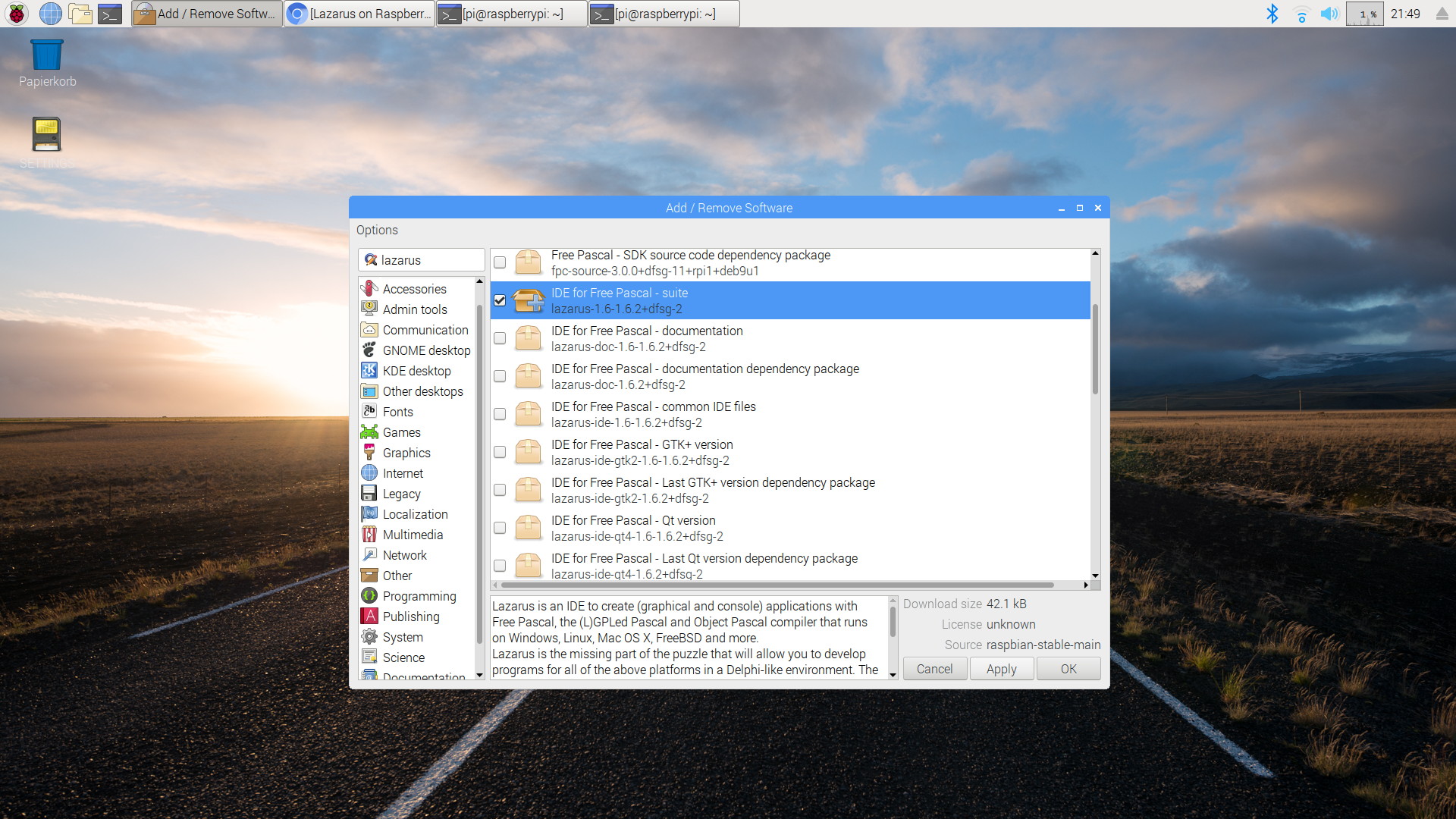
Step 2: Install Lazarus
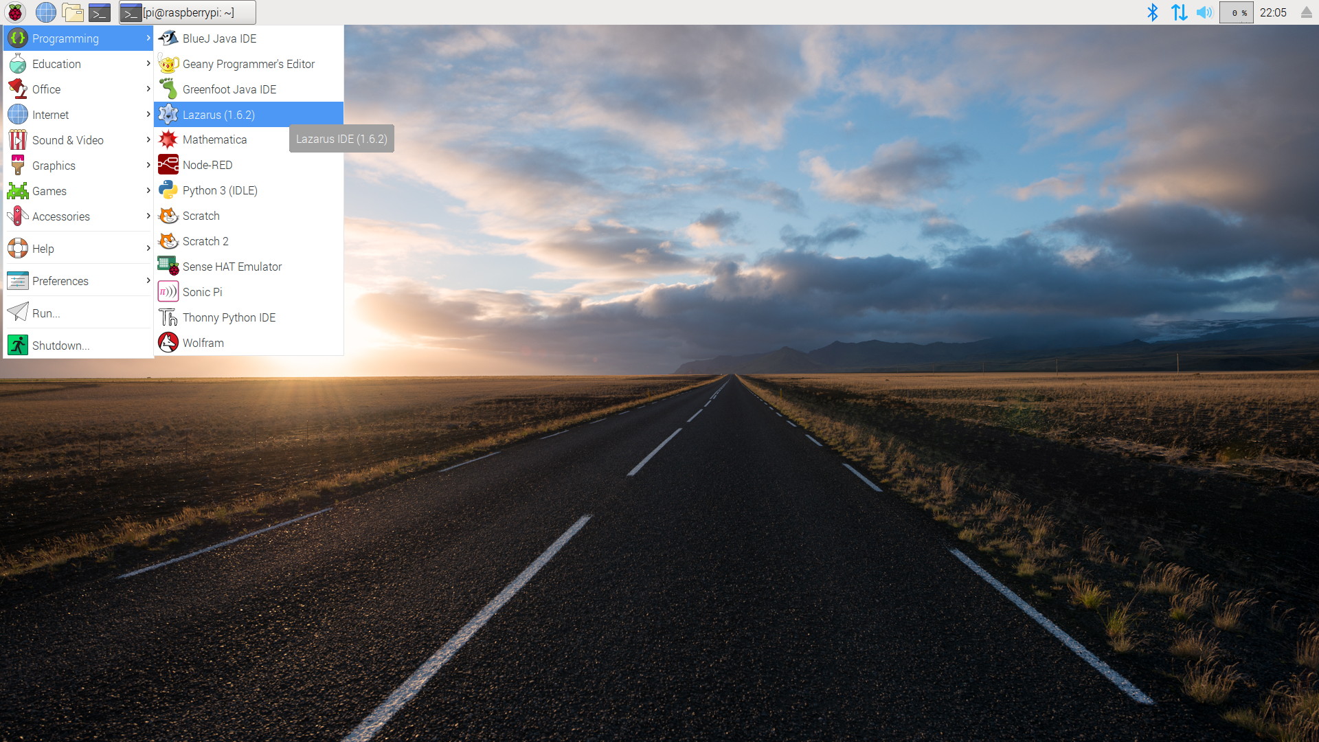
Lazarus is now available in the global "Programming" menu
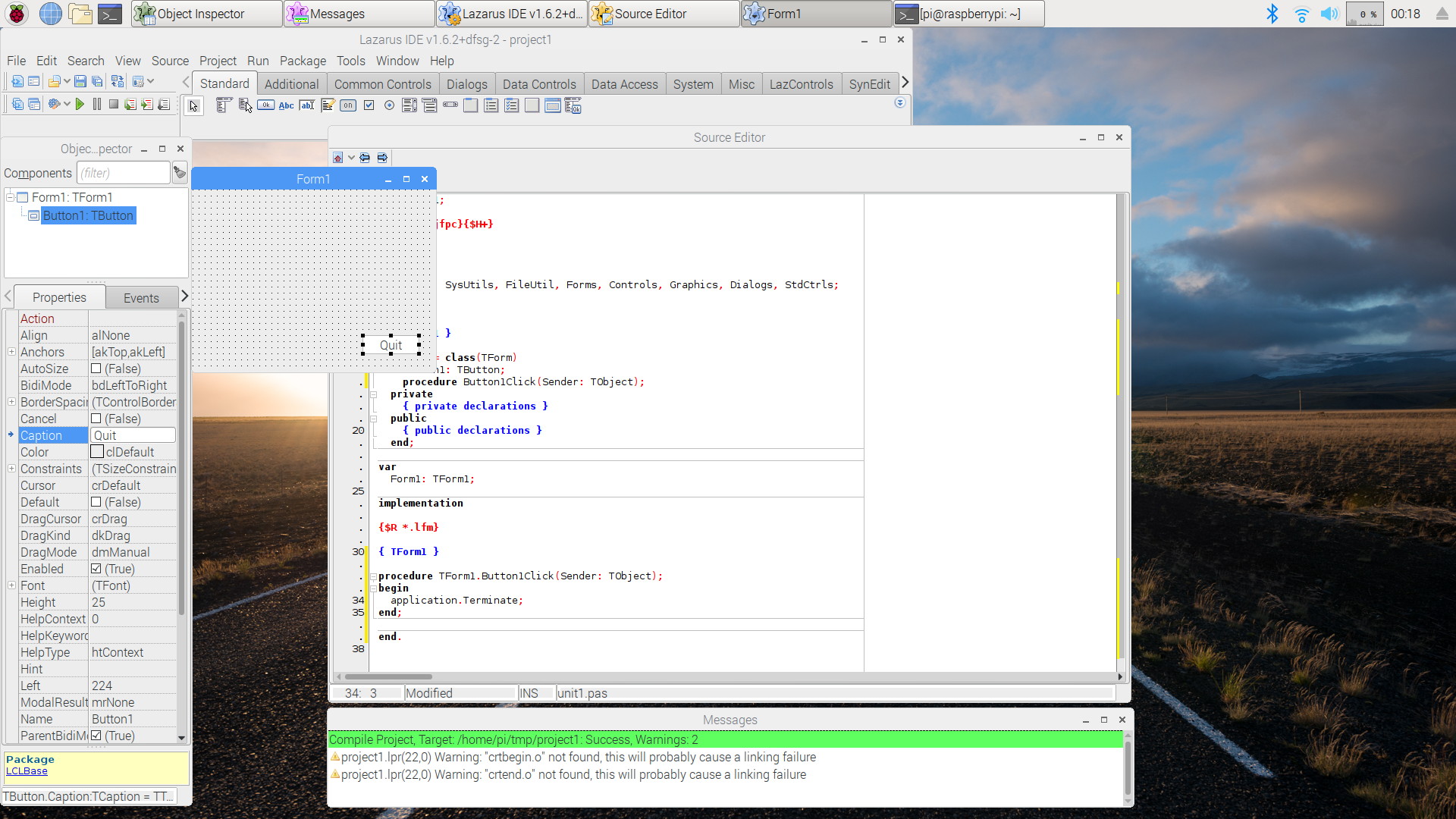
A simple session with Lazarus on Raspbian Stretch.


Old Raspbian versions
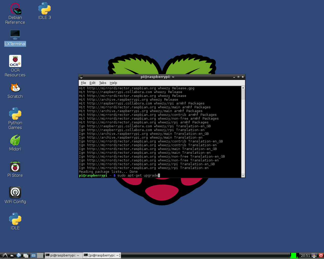
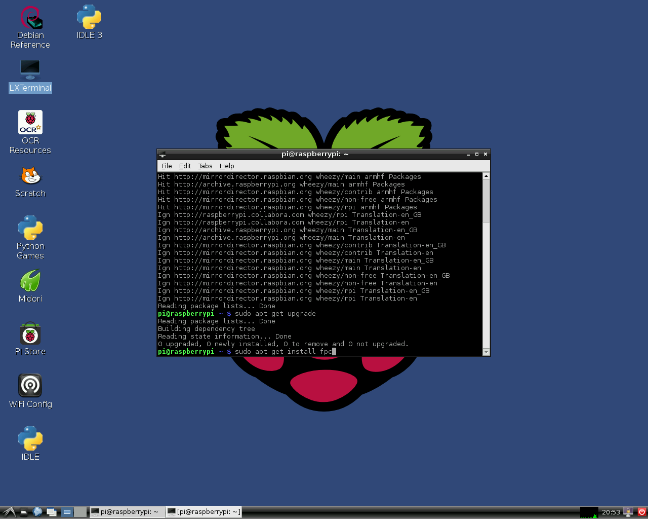
Old versions of Raspbian OS (e.g. Wheezy) don't provide the graphical installer. However, it is easy to install Lazarus and Free Pascal anyway. In order to do this simply open a terminal window and type:
sudo apt-get update
sudo apt-get upgrade
sudo apt-get install fpc

sudo apt-get install lazarus
Note: if sudo apt-get install fpc returns unable to find fpc, repeat the sudo apt-get update
This installs a precompiled, stable version of FPC and Lazarus on the Raspberry Pi. Of course, a network connection is required. Installation may take about 30 minutes, but major portions of this process take place automatically. After installation you may instantly start Lazarus from the "Programming" section of the LXDE start menu.
Installation 1
Installation 2
Installation 3

Installation 4


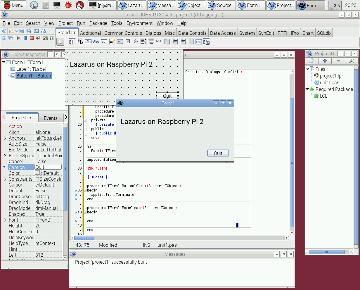
Lazarus "out of the box" on Raspberry Pi 2

Cross compiling for the Raspberry Pi from Windows
1. Using fpcup
One way is to use fpcup to set up a cross compiler; follow these instructions: fpcup#Linux_ARM_cross_compiler
2. Using scripts
Alternatively, for a more manual approach using batch files, you can follow these steps.
2.1 Prerequisites
FPC 2.7.1 or higher installed with source code
Install the Windows version from the Linaro binutils for linux gnueabihf into %FPCPATH%/bin/win32-armhf-linux [1]
2.2 Example Windows Batch file (adapt paths as needed)
set PATH=C:\pp\bin\i386-win32;%PATH%;
set FPCMAKEPATH=C:/pp
set FPCPATH=C:/pp
set OUTPATH=C:/pp271
%FPCMAKEPATH%/bin/i386-win32/make distclean OS_TARGET=linux CPU_TARGET=arm  CROSSBINDIR=%FPCPATH%/bin/win32-armhf-linux CROSSOPT="-CpARMV6 -CfVFPV2 -OoFASTMATH" FPC=%FPCPATH%/bin/i386-win32/ppc386.exe

%FPCMAKEPATH%/bin/i386-win32/make all OS_TARGET=linux CPU_TARGET=arm CROSSBINDIR=%FPCPATH%/bin/win32-armhf-linux CROSSOPT="-CpARMV6 -CfVFPV2 -OoFASTMATH" FPC=%FPCPATH%/bin/i386-win32/ppc386.exe
if errorlevel 1 goto quit
%FPCMAKEPATH%/bin/i386-win32/make crossinstall CROSSBINDIR=%FPCPATH%/bin/win32-armhf-linux CROSSOPT="-CpARMV6 -CfVFPV2 -OoFASTMATH" OS_TARGET=linux CPU_TARGET=arm FPC=%FPCPATH%/bin/i386-win32/ppc386.exe INSTALL_BASEDIR=%OUTPATH%

:quit
pause
With the resulting ppcrossarm.exe and ARM RTL you will be able to build a cross Lazarus version as usual and compile FPC projects for the Raspberry Pi and other armhf devices.
Remember that not all - especially Windows - libraries are available for Linux arm.
Cross compiling for the Raspberry Pi from Linux
Please see this page https://wiki.freepascal.org/Cross_Compile_to_RasPi_from_Linux
Compiling from sources
You may want to compile Lazarus from subversion sources. See Michell Computing: Lazarus on the Raspberry Pi for details.
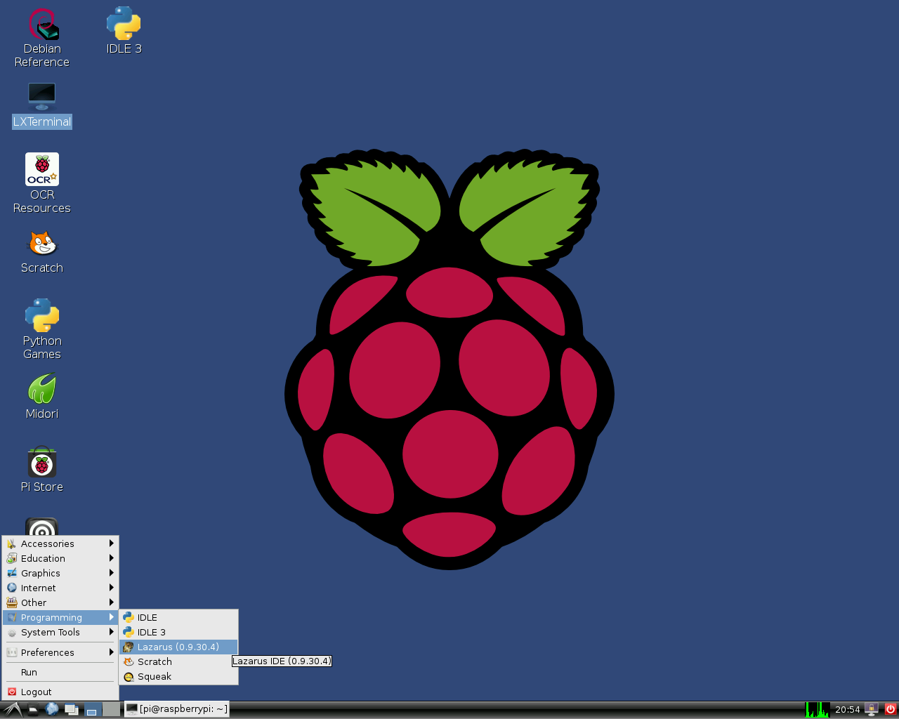
How to start Lazarus in Raspbian Wheezy
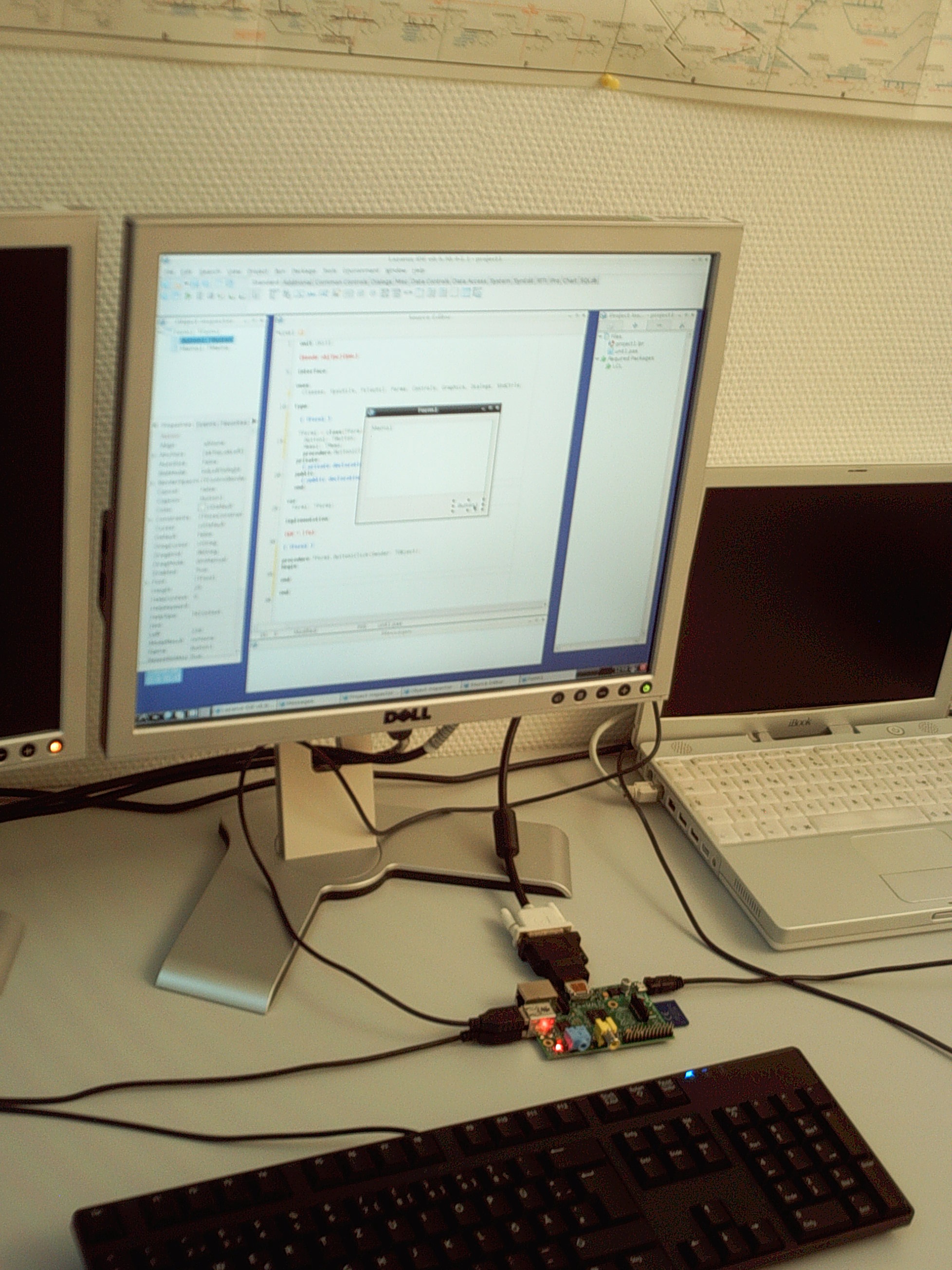
Lazarus on Raspberry Pi
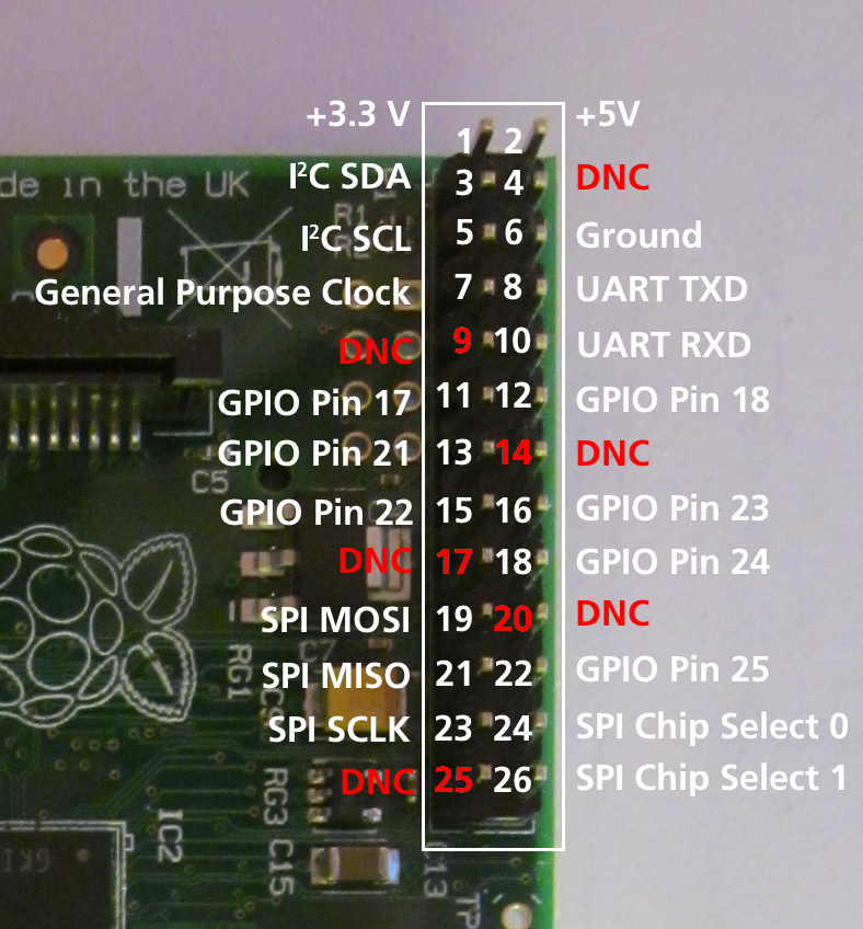
Numbering of GPIO pins


Compiling from sources on Raspberry with Gentoo (and other distro)
If you want to install the latest stable release of fpc and, additional and isolated, the trunk fpc compiler: you can read the following guide. It was written using gentoo but this guide will be useful with any distro: Install fpc on Raspberry with Gentoo
Accessing external hardware

One of the goals in the development of Raspberry Pi was to facilitate effortless access to external devices like sensors and actuators. There are many ways to access the I/O facilities from Lazarus and Free Pascal:
- Direct access using the BaseUnix unit
- Access through encapsulated shell calls
- Access through the wiringPi library.
- Access through Unit rpi_hal.
- Access through Unit PiGpio.
- Access through the PascalIO library.
- Access through the PXL library.
Native hardware access


This method provides access to external hardware that doesn't require additional libraries. The only requirement is the BaseUnix library that is part of Free Pascal's RTL.
Switching a device via the GPIO port
The following example lists a simple program that controls the GPIO pin 17 as output to switch an LED, transistor or relays. This program contains a ToggleBox with name GPIO17ToggleBox and for logging return codes a TMemo called LogMemo.
For the example, the anode of a LED has been connected with Pin 11 on the Pi's connector (corresponding to GPIO pin 17 of the BCM2835 SOC) and the LED's cathode was wired via a 68 Ohm resistor to pin 6 of the connector (GND) as previously described by Upton and Halfacree. Subsequently, the LED may be switched on and off with the application's toggle box.
The code may at first require to be run as root, i.e. either from a root account (not recommended) or via su. A better option is to add the user to the gpio group, the i2c group and the spi group.
sudo adduser pi gpio
sudo adduser pi i2c
sudo adduser pi spi
Controlling unit:
unit Unit1;

{Demo application for GPIO on Raspberry Pi}
{Inspired by the Python input/output demo application by Gareth Halfacree}
{written for the Raspberry Pi User Guide, ISBN 978-1-118-46446-5}

{$mode objfpc}{$H+}

interface

uses
  Classes, SysUtils, FileUtil, Forms, Controls, Graphics, Dialogs, StdCtrls,
  Unix, BaseUnix;

type

  { TForm1 }

  TForm1 = class(TForm)
    LogMemo: TMemo;
    GPIO17ToggleBox: TToggleBox;
    procedure FormActivate(Sender: TObject);
    procedure FormClose(Sender: TObject; var CloseAction: TCloseAction);
    procedure GPIO17ToggleBoxChange(Sender: TObject);
  private
    { private declarations }
  public
    { public declarations }
  end;

const
  PIN_17: PChar = '17';
  PIN_ON: PChar = '1';
  PIN_OFF: PChar = '0';
  OUT_DIRECTION: PChar = 'out';

var
  Form1: TForm1;
  gReturnCode: longint; {stores the result of the IO operation}

implementation

{$R *.lfm}

{ TForm1 }

procedure TForm1.FormActivate(Sender: TObject);
var
  fileDesc: integer;
begin
  { Prepare SoC pin 17 (pin 11 on GPIO port) for access: }
  try
    fileDesc := fpopen('/sys/class/gpio/export', O_WrOnly);
    gReturnCode := fpwrite(fileDesc, PIN_17[0], 2);
    LogMemo.Lines.Add(IntToStr(gReturnCode));
  finally
    gReturnCode := fpclose(fileDesc);
    LogMemo.Lines.Add(IntToStr(gReturnCode));
  end;
  { Set SoC pin 17 as output: }
  try
    fileDesc := fpopen('/sys/class/gpio/gpio17/direction', O_WrOnly);
    gReturnCode := fpwrite(fileDesc, OUT_DIRECTION[0], 3);
    LogMemo.Lines.Add(IntToStr(gReturnCode));
  finally
    gReturnCode := fpclose(fileDesc);
    LogMemo.Lines.Add(IntToStr(gReturnCode));
  end;
end;

procedure TForm1.FormClose(Sender: TObject; var CloseAction: TCloseAction);
var
  fileDesc: integer;
begin
  { Free SoC pin 17: }
  try
    fileDesc := fpopen('/sys/class/gpio/unexport', O_WrOnly);
    gReturnCode := fpwrite(fileDesc, PIN_17[0], 2);
    LogMemo.Lines.Add(IntToStr(gReturnCode));
  finally
    gReturnCode := fpclose(fileDesc);
    LogMemo.Lines.Add(IntToStr(gReturnCode));
  end;
end;

procedure TForm1.GPIO17ToggleBoxChange(Sender: TObject);
var
  fileDesc: integer;
begin
  if GPIO17ToggleBox.Checked then
  begin
    { Swith SoC pin 17 on: }
    try
      fileDesc := fpopen('/sys/class/gpio/gpio17/value', O_WrOnly);
      gReturnCode := fpwrite(fileDesc, PIN_ON[0], 1);
      LogMemo.Lines.Add(IntToStr(gReturnCode));
    finally
      gReturnCode := fpclose(fileDesc);
      LogMemo.Lines.Add(IntToStr(gReturnCode));
    end;
  end
  else
  begin
    { Switch SoC pin 17 off: }
    try
      fileDesc := fpopen('/sys/class/gpio/gpio17/value', O_WrOnly);
      gReturnCode := fpwrite(fileDesc, PIN_OFF[0], 1);
      LogMemo.Lines.Add(IntToStr(gReturnCode));
    finally
      gReturnCode := fpclose(fileDesc);
      LogMemo.Lines.Add(IntToStr(gReturnCode));
    end;
  end;
end;

end.
Main program:
program io_test;

{$mode objfpc}{$H+}

uses
  {$IFDEF UNIX}{$IFDEF UseCThreads}
  cthreads,
  {$ENDIF}{$ENDIF}
  Interfaces, // this includes the LCL widgetset
  Forms, Unit1
  { you can add units after this };

{$R *.res}

begin
  Application.Initialize;
  Application.CreateForm(TForm1, Form1);
  Application.Run;
end.
Reading the status of a pin


Of course it is also possible to read the status of e.g. a switch that is connected to the GPIO port.
The following simple example is very similar to the previous one. It controls the GPIO pin 18 as input for a binary device like a switch, transistor or relais. This program contains a CheckBox with name GPIO18CheckBox and for logging return codes a TMemo called LogMemo.
For the example, one pole of a push-button has been connected to Pin 12 on the Pi's connector (corresponding to GPIO pin 18 of the BCM2835 SOC) and via a 10k Ohm pull-up resistor with pin 1 (+3.3V, see wiring diagram). The other pole has been wired to pin 6 of the connector (GND). The program senses the status of the button and correspondingly switches the checkbox on or off, respectively.
Note that the potential of pin 18 is high if the button is released (by virtue of the connection to pin 1 via the pull-up resistor) and low if it is pressed (since in this situation pin 18 is connected to GND via the switch). Therefore, the GPIO pin signals 0 if the button is pressed and 1 if it is released.
This program has again to be executed as root.
Controlling unit:
unit Unit1;

{Demo application for GPIO on Raspberry Pi}
{Inspired by the Python input/output demo application by Gareth Halfacree}
{written for the Raspberry Pi User Guide, ISBN 978-1-118-46446-5}

{This application reads the status of a push-button}

{$mode objfpc}{$H+}

interface

uses
  Classes, SysUtils, FileUtil, Forms, Controls, Graphics, Dialogs, StdCtrls,
  ButtonPanel, Unix, BaseUnix;

type

  { TForm1 }

  TForm1 = class(TForm)
    ApplicationProperties1: TApplicationProperties;
    GPIO18CheckBox: TCheckBox;
    LogMemo: TMemo;
    procedure ApplicationProperties1Idle(Sender: TObject; var Done: Boolean);
    procedure FormActivate(Sender: TObject);
    procedure FormClose(Sender: TObject; var CloseAction: TCloseAction);
  private
    { private declarations }
  public
    { public declarations }
  end;

const
  PIN_18: PChar = '18';
  IN_DIRECTION: PChar = 'in';

var
  Form1: TForm1;
  gReturnCode: longint; {stores the result of the IO operation}

implementation

{$R *.lfm}

{ TForm1 }

procedure TForm1.FormActivate(Sender: TObject);
var
  fileDesc: integer;
begin
  { Prepare SoC pin 18 (pin 12 on GPIO port) for access: }
  try
    fileDesc := fpopen('/sys/class/gpio/export', O_WrOnly);
    gReturnCode := fpwrite(fileDesc, PIN_18[0], 2);
    LogMemo.Lines.Add(IntToStr(gReturnCode));
  finally
    gReturnCode := fpclose(fileDesc);
    LogMemo.Lines.Add(IntToStr(gReturnCode));
  end;
  { Set SoC pin 18 as input: }
  try
    fileDesc := fpopen('/sys/class/gpio/gpio18/direction', O_WrOnly);
    gReturnCode := fpwrite(fileDesc, IN_DIRECTION[0], 2);
    LogMemo.Lines.Add(IntToStr(gReturnCode));
  finally
    gReturnCode := fpclose(fileDesc);
    LogMemo.Lines.Add(IntToStr(gReturnCode));
  end;
end;

procedure TForm1.ApplicationProperties1Idle(Sender: TObject; var Done: Boolean);
var
  fileDesc: integer;
  buttonStatus: string[1] = '1';
begin
  try
    { Open SoC pin 18 (pin 12 on GPIO port) in read-only mode: }
    fileDesc := fpopen('/sys/class/gpio/gpio18/value', O_RdOnly);
    if fileDesc > 0 then
    begin
      { Read status of this pin (0: button pressed, 1: button released): }
      gReturnCode := fpread(fileDesc, buttonStatus[1], 1);
      LogMemo.Lines.Add(IntToStr(gReturnCode) + ': ' + buttonStatus);
      LogMemo.SelStart := Length(LogMemo.Lines.Text) - 1;
      if buttonStatus = '0' then
        GPIO18CheckBox.Checked := true
      else
        GPIO18CheckBox.Checked := false;
    end;
  finally
    { Close SoC pin 18 (pin 12 on GPIO port) }
    gReturnCode := fpclose(fileDesc);
    LogMemo.Lines.Add(IntToStr(gReturnCode));
    LogMemo.SelStart := Length(LogMemo.Lines.Text) - 1;
  end;
end;

procedure TForm1.FormClose(Sender: TObject; var CloseAction: TCloseAction);
var
  fileDesc: integer;
begin
  { Free SoC pin 18: }
  try
    fileDesc := fpopen('/sys/class/gpio/unexport', O_WrOnly);
    gReturnCode := fpwrite(fileDesc, PIN_18[0], 2);
    LogMemo.Lines.Add(IntToStr(gReturnCode));
  finally
    gReturnCode := fpclose(fileDesc);
    LogMemo.Lines.Add(IntToStr(gReturnCode));
  end;
end;

end.
The main program is identical to that of the example from above.
Hardware access via encapsulated shell calls
Another way to access the hardware is by encapsulating terminal commands. This is achieved by using the fpsystem function. This method gives access to functions that are not supported by the BaseUnix unit. The following code implements a program that has the same functionality as the program resulting from the first listing above.
Controlling unit:
unit Unit1;

{Demo application for GPIO on Raspberry Pi}
{Inspired by the Python input/output demo application by Gareth Halfacree}
{written for the Raspberry Pi User Guide, ISBN 978-1-118-46446-5}

{$mode objfpc}{$H+}

interface

uses
  Classes, SysUtils, FileUtil, Forms, Controls, Graphics, Dialogs, StdCtrls, Unix;

type

  { TForm1 }

  TForm1 = class(TForm)
    LogMemo: TMemo;
    GPIO17ToggleBox: TToggleBox;
    procedure FormActivate(Sender: TObject);
    procedure FormClose(Sender: TObject; var CloseAction: TCloseAction);
    procedure GPIO17ToggleBoxChange(Sender: TObject);
  private
    { private declarations }
  public
    { public declarations }
  end;

var
  Form1: TForm1;
  gReturnCode: longint; {stores the result of the IO operation}

implementation

{$R *.lfm}

{ TForm1 }

procedure TForm1.FormActivate(Sender: TObject);
begin
  { Prepare SoC pin 17 (pin 11 on GPIO port) for access: }
  gReturnCode := fpsystem('echo "17" > /sys/class/gpio/export');
  LogMemo.Lines.Add(IntToStr(gReturnCode));
  { Set SoC pin 17 as output: }
  gReturnCode := fpsystem('echo "out" > /sys/class/gpio/gpio17/direction');
  LogMemo.Lines.Add(IntToStr(gReturnCode));
end;

procedure TForm1.FormClose(Sender: TObject; var CloseAction: TCloseAction);
begin
  { Free SoC pin 17: }
  gReturnCode := fpsystem('echo "17" > /sys/class/gpio/unexport');
  LogMemo.Lines.Add(IntToStr(gReturnCode));
end;

procedure TForm1.GPIO17ToggleBoxChange(Sender: TObject);
begin
  if GPIO17ToggleBox.Checked then
  begin
    { Swith SoC pin 17 on: }
    gReturnCode := fpsystem('echo "1" > /sys/class/gpio/gpio17/value');
    LogMemo.Lines.Add(IntToStr(gReturnCode));
  end
  else
  begin
    { Switch SoC pin 17 off: }
    gReturnCode := fpsystem('echo "0" > /sys/class/gpio/gpio17/value');
    LogMemo.Lines.Add(IntToStr(gReturnCode));
  end;
end;

end.
The main program is identical to that of the example above. This program has to be executed with root privileges, too.
wiringPi procedures and functions
Alex Schaller's wrapper unit for Gordon Henderson's Arduino compatible wiringPi library provides a numbering scheme that resembles that of Arduino boards.
Function wiringPiSetup:longint: Initializes wiringPi system using the wiringPi pin numbering scheme.
Procedure wiringPiGpioMode(mode:longint): Initializes wiringPi system with the Broadcom GPIO pin numbering scheme.
Procedure pullUpDnControl(pin:longint; pud:longint): controls the internal pull-up/down resistors on a GPIO pin.
Procedure pinMode(pin:longint; mode:longint): sets the mode of a pin to either INPUT, OUTPUT, or PWM_OUTPUT.
Procedure digitalWrite(pin:longint; value:longint): sets an output bit.
Procedure pwmWrite(pin:longint; value:longint): sets an output PWM value between 0 and 1024.
Function digitalRead(pin:longint):longint: reads the value of a given Pin, returning 1 or 0.
Procedure delay(howLong:dword): waits for at least howLong milliseconds.
Procedure delayMicroseconds(howLong:dword): waits for at least howLong microseconds.
Function millis:dword: returns the number of milliseconds since the program called one of the wiringPiSetup functions.
rpi_hal-Hardware Abstraction Library (GPIO, I2C and SPI functions and procedures)
This Unit with around 1700 Lines of Code provided by Stefan Fischer, delivers procedures and functions to access the rpi HW I2C, SPI and GPIO:
Just an excerpt of the available functions and procedures:
procedure gpio_set_pin (pin:longword;highlevel:boolean); { Set RPi GPIO pin to high or low level; Speed @ 700MHz -> 0.65MHz }
function gpio_get_PIN (pin:longword):boolean; { Get RPi GPIO pin Level is true when Pin level is '1'; false when '0'; Speed @ 700MHz -> 1.17MHz }
procedure gpio_set_input (pin:longword); { Set RPi GPIO pin to input direction }
procedure gpio_set_output(pin:longword); { Set RPi GPIO pin to output direction }
procedure gpio_set_alt (pin,altfunc:longword); { Set RPi GPIO pin to alternate function nr. 0..5 }
procedure gpio_set_gppud (mask:longword); { set RPi GPIO Pull-up/down Register (GPPUD) with mask }
...
function rpi_snr :string; { delivers SNR: 0000000012345678 }
function rpi_hw :string; { delivers Processor Type: BCM2708 }
function rpi_proc:string; { ARMv6-compatible processor rev 7 (v6l) }
...
function i2c_bus_write(baseadr,reg:word; var data:databuf_t; lgt:byte; testnr:integer) : integer;
function i2c_bus_read (baseadr,reg:word; var data:databuf_t; lgt:byte; testnr:integer) : integer;
function i2c_string_read(baseadr,reg:word; var data:databuf_t; lgt:byte; testnr:integer) : string;
function i2c_string_write(baseadr,reg:word; s:string; testnr:integer) : integer;
...
procedure SPI_Write(devnum:byte; reg,data:word);
function SPI_Read(devnum:byte; reg:word) : byte;
procedure SPI_BurstRead2Buffer (devnum,start_reg:byte; xferlen:longword);
procedure SPI_BurstWriteBuffer (devnum,start_reg:byte; xferlen:longword); { Write 'len' Bytes from Buffer SPI Dev startig at address 'reg' }
...
Test Program (testrpi.pas):
//Simple Test program, which is using rpi_hal;

  program testrpi;
  uses rpi_hal;
  begin
    writeln('Show CPU-Info, RPI-HW-Info and Registers:');
    rpi_show_all_info;
    writeln('Let Status LED Blink. Using GPIO functions:');
    GPIO_PIN_TOGGLE_TEST;
    writeln('Test SPI Read function. (piggy back board with installed RFM22B Module is required!)');
    Test_SPI;
  end.
PiGpio Low-level native pascal unit (GPIO control instead of wiringPi c library)
This Unit (pigpio.pas[2]) with 270 Lines of Code provided by Gabor Szollosi, works very fast (for ex. GPIO pin output switching frequency 8 MHz) :
unit PiGpio;
{
 BCM2835 GPIO Registry Driver, also can use to manipulate cpu other registry areas

 This code is tested only Broadcom bcm2835 cpu, different arm cpus may need different
 gpio driver implementation

 2013 Gabor Szollosi
}
{$mode objfpc}{$H+}

interface

uses
  Classes, SysUtils;

const
  REG_GPIO = $3F000;// bcm2835 gpio register 0x2000 0000 (RPi1), 0x3F00 0000 (RPi2)
  // new fpMap uses page offset, one page is 4096 bytes = 0x1000 so simply calculate 0x2000 0000 / 0x1000  = 0x2000 0
  PAGE_SIZE = 4096;
  BLOCK_SIZE = 4096;
  // The BCM2835 has 54 GPIO pins.
  //	BCM2835 data sheet, Page 90 onwards.
  //	There are 6 control registers, each control the functions of a block
  //	of 10 pins.

  CLOCK_BASE = (REG_GPIO + $101);
  GPIO_BASE =  (REG_GPIO + $200);
  GPIO_PWM =   (REG_GPIO + $20C);

     INPUT = 0;
     OUTPUT = 1;
     PWM_OUTPUT = 2;
     LOW = False;
     HIGH = True;
     PUD_OFF = 0;
     PUD_DOWN = 1;
     PUD_UP = 2;

   // PWM

  PWM_CONTROL = 0;
  PWM_STATUS  = 4;
  PWM0_RANGE  = 16;
  PWM0_DATA   = 20;
  PWM1_RANGE  = 32;
  PWM1_DATA   = 36;

  PWMCLK_CNTL =	160;
  PWMCLK_DIV  =	164;

  PWM1_MS_MODE    = $8000;  // Run in MS mode
  PWM1_USEFIFO    = $2000; // Data from FIFO
  PWM1_REVPOLAR   = $1000;  // Reverse polarity
  PWM1_OFFSTATE   = $0800;  // Ouput Off state
  PWM1_REPEATFF   = $0400;  // Repeat last value if FIFO empty
  PWM1_SERIAL     = $0200;  // Run in serial mode
  PWM1_ENABLE     = $0100;  // Channel Enable

  PWM0_MS_MODE    = $0080;  // Run in MS mode
  PWM0_USEFIFO    = $0020;  // Data from FIFO
  PWM0_REVPOLAR   = $0010;  // Reverse polarity
  PWM0_OFFSTATE   = $0008;  // Ouput Off state
  PWM0_REPEATFF   = $0004;  // Repeat last value if FIFO empty
  PWM0_SERIAL     = $0002;  // Run in serial mode
  PWM0_ENABLE     = $0001;  // Channel Enable


type

  { TIoPort }

  TIoPort = class // IO bank object
  private         //

    //function get_pinDirection(aPin: TGpIoPin): TGpioPinConf;

  public
   FGpio: ^LongWord;
   FClk: ^LongWord;
   FPwm: ^LongWord;
   procedure SetPinMode(gpin, mode: byte);
   function GetBit(gpin : byte):boolean;inline; // gets pin bit}
   procedure ClearBit(gpin : byte);inline;// write pin to 0
   procedure SetBit(gpin : byte);inline;// write pin to 1
   procedure SetPullMode(gpin, mode: byte);
   procedure PwmWrite(gpin : byte; value : LongWord);inline;// write pin to pwm value
  end;

  { TIoDriver }

  TIoDriver = class
  private

  public
    destructor Destroy;override;
    function MapIo:boolean;// creates io memory mapping
    procedure UnmapIoRegisrty(FMap: TIoPort);// close io memory mapping
    function CreatePort(PortGpio, PortClk, PortPwm: LongWord):TIoPort; // create new IO port
  end;

var

    fd: integer;// /dev/mem file handle
procedure delayNanoseconds (howLong : LongWord);


implementation

uses
  baseUnix, Unix;

procedure delayNanoseconds (howLong : LongWord);
var
  sleeper, dummy : timespec;
begin
  sleeper.tv_sec  := 0 ;
  sleeper.tv_nsec := howLong ;
  fpnanosleep (@sleeper,@dummy) ;
end;
{ TIoDriver }
//*******************************************************************************
destructor TIoDriver.Destroy;
begin
  inherited Destroy;
end;
//*******************************************************************************
function TIoDriver.MapIo: boolean;
begin
 Result := True;
 fd := fpopen('/dev/mem', O_RdWr or O_Sync); // Open the master /dev/memory device
  if fd < 0 then
  begin
    Result := False; // unsuccessful memory mapping
  end;
 //
end;
//*******************************************************************************
procedure TIoDriver.UnmapIoRegisrty(FMap:TIoPort);
begin
  if FMap.FGpio <> nil then
 begin
   fpMUnmap(FMap.FGpio,PAGE_SIZE);
   FMap.FGpio := Nil;
 end;
 if FMap.FClk <> nil then
 begin
   fpMUnmap(FMap.FClk,PAGE_SIZE);
   FMap.FClk := Nil;
 end;
 if FMap.FPwm <> nil then
 begin
   fpMUnmap(FMap.FPwm ,PAGE_SIZE);
   FMap.FPwm := Nil;
 end;
end;
//*******************************************************************************
function TIoDriver.CreatePort(PortGpio, PortClk, PortPwm: LongWord): TIoPort;
begin
  Result := TIoPort.Create;// new io port, pascal calls new fpMap, where offst is page sized 4096 bytes!!!
  Result.FGpio := FpMmap(Nil, PAGE_SIZE, PROT_READ or PROT_WRITE, MAP_SHARED, fd, PortGpio); // port config gpio memory
  Result.FClk:= FpMmap(Nil, PAGE_SIZE, PROT_READ or PROT_WRITE, MAP_SHARED, fd, PortClk);; // port clk
  Result.FPwm:= FpMmap(Nil, PAGE_SIZE, PROT_READ or PROT_WRITE, MAP_SHARED, fd, PortPwm);; // port pwm
end;
//*******************************************************************************
procedure TIoPort.SetPinMode(gpin, mode: byte);
var
  fSel, shift, alt : byte;
  gpiof, clkf, pwmf : ^LongWord;
begin
  fSel := (gpin div 10)*4 ;  //Select Gpfsel 0 to 5 register
  shift := (gpin mod 10)*3 ;  //0-9 pin shift
  gpiof := Pointer(LongWord(Self.FGpio)+fSel);
  if (mode = INPUT) then
    gpiof^ := gpiof^ and ($FFFFFFFF - (7 shl shift))  //7 shl shift komplemens - Sets bits to zero = input
  else if (mode = OUTPUT) then
  begin
    gpiof^ := gpiof^ and ($FFFFFFFF - (7 shl shift)) or (1 shl shift);
  end
  else if (mode = PWM_OUTPUT) then
  begin
    Case gpin of
      12,13,40,41,45 : alt:= 4 ;
      18,19          : alt:= 2 ;
      else alt:= 0 ;
    end;
    If alt > 0 then
    begin
      gpiof^ := gpiof^ and ($FFFFFFFF - (7 shl shift)) or (alt shl shift);
      clkf := Pointer(LongWord(Self.FClk)+PWMCLK_CNTL);
      clkf^ := $5A000011 or (1 shl 5) ;                  //stop clock
      delayNanoseconds(200);
      clkf := Pointer(LongWord(Self.FClk)+PWMCLK_DIV);
      clkf^ := $5A000000 or (32 shl 12) ;	// set pwm clock div to 32 (19.2/3 = 600KHz)
      clkf := Pointer(LongWord(Self.FClk)+PWMCLK_CNTL);
      clkf^ := $5A000011 ;                               //start clock
      Self.ClearBit(gpin);
      pwmf := Pointer(LongWord(Self.FPwm)+PWM_CONTROL);
      pwmf^ := 0 ;		 	        // Disable PWM
      delayNanoseconds(200);
      pwmf := Pointer(LongWord(Self.FPwm)+PWM0_RANGE);
      pwmf^ := $400 ;                             //max: 1023
      delayNanoseconds(200);
      pwmf := Pointer(LongWord(Self.FPwm)+PWM1_RANGE);
      pwmf^ := $400 ;                             //max: 1023
      delayNanoseconds(200);
      // Enable PWMs
      pwmf := Pointer(LongWord(Self.FPwm)+PWM0_DATA);
      pwmf^ := 0 ;                                //start value
      pwmf := Pointer(LongWord(Self.FPwm)+PWM1_DATA);
      pwmf^ := 0 ;                                //start value
      pwmf := Pointer(LongWord(Self.FPwm)+PWM_CONTROL);
      pwmf^ := PWM0_ENABLE or PWM1_ENABLE ;
    end;
  end;
end;
//*******************************************************************************
procedure TIoPort.SetBit(gpin : byte);
var
   gpiof : ^LongWord;
begin
  gpiof := Pointer(LongWord(Self.FGpio) + 28 + (gpin shr 5) shl 2);
  gpiof^ := 1 shl gpin;
end;
//*******************************************************************************
procedure TIoPort.ClearBit(gpin : byte);
var
   gpiof : ^LongWord;
begin
  gpiof := Pointer(LongWord(Self.FGpio) + 40 + (gpin shr 5) shl 2);
  gpiof^ := 1 shl gpin;
end;
//*******************************************************************************
function TIoPort.GetBit(gpin : byte):boolean;
var
   gpiof : ^LongWord;
begin
  gpiof := Pointer(LongWord(Self.FGpio) + 52 + (gpin shr 5) shl 2);
  if (gpiof^ and (1 shl gpin)) = 0 then Result := False else Result := True;
end;
//*******************************************************************************
procedure TIoPort.SetPullMode(gpin, mode: byte);
var
   pudf, pudclkf : ^LongWord;
begin
  pudf := Pointer(LongWord(Self.FGpio) + 148 );
  pudf^ := mode;   //mode = 0, 1, 2 :Off, Down, Up
  delayNanoseconds(200);
  pudclkf := Pointer(LongWord(Self.FGpio) + 152 + (gpin shr 5) shl 2);
  pudclkf^ := 1 shl gpin ;
  delayNanoseconds(200);
  pudf^ := 0 ;
  pudclkf^ := 0 ;
end;
//*******************************************************************************
procedure TIoPort.PwmWrite(gpin : byte; value : Longword);
var
   pwmf : ^LongWord;
   port : byte;
begin
  Case gpin of
      12,18,40 : port:= PWM0_DATA ;
      13,19,41,45 : port:= PWM1_DATA ;
      else exit;
  end;
  pwmf := Pointer(LongWord(Self.FPwm) + port);
  pwmf^ := value and $FFFFFBFF; // $400 complemens
end;
//*******************************************************************************
end.
Controlling Lazarus unit:(Project files[3])
unit Unit1;

{Demo application for GPIO on Raspberry Pi}
{Inspired by the Python input/output demo application by Gareth Halfacree}
{written for the Raspberry Pi User Guide, ISBN 978-1-118-46446-5}

{$mode objfpc}{$H+}

interface

uses
  Classes, SysUtils, FileUtil, Forms, Controls, Graphics, Dialogs, StdCtrls,
  ExtCtrls, Unix, PiGpio;

type

  { TForm1 }

  TForm1 = class(TForm)
    GPIO25In: TButton;
    SpeedButton: TButton;
    LogMemo: TMemo;
    GPIO23switch: TToggleBox;
    Timer1: TTimer;
    GPIO18Pwm: TToggleBox;
    Direction: TToggleBox;
    procedure DirectionChange(Sender: TObject);
    procedure GPIO18PwmChange(Sender: TObject);
    procedure GPIO25InClick(Sender: TObject);
    procedure FormActivate(Sender: TObject);
    procedure FormClose(Sender: TObject; var CloseAction: TCloseAction);
    procedure GPIO23switchChange(Sender: TObject);
    procedure SpeedButtonClick(Sender: TObject);
    procedure Timer1Timer(Sender: TObject);
  private
    { private declarations }
  public
    { public declarations }
  end;

const
     INPUT = 0;
     OUTPUT = 1;
     PWM_OUTPUT = 2;
     LOW = False;
     HIGH = True;
     PUD_OFF = 0;
     PUD_DOWN = 1;
     PUD_UP = 2;
 // Convert Raspberry Pi P1 pins (Px) to GPIO port
     P3 = 0;
     P5 = 1;
     P7 = 4;
     P8 = 14;
     P10 = 15;
     P11 = 17;
     P12 = 18;
     P13 = 21;
     P15 = 22;
     P16 = 23;
     P18 = 24;
     P19 = 10;
     P21 = 9;
     P22 = 25;
     P23 = 11;
     P24 = 8;
     P26 = 7;

var
  Form1: TForm1;
  GPIO_Driver: TIoDriver;
  GpF: TIoPort;
  PWM :Boolean;
  i, d : integer;
  Pin,Pout,Ppwm : byte;

implementation

{$R *.lfm}

{ TForm1 }

procedure TForm1.FormActivate(Sender: TObject);
begin
  if not GPIO_Driver.MapIo then
  begin
     LogMemo.Lines.Add('Error mapping gpio registry');
  end
  else
  begin
    GpF := GpIo_Driver.CreatePort(GPIO_BASE, CLOCK_BASE, GPIO_PWM);
  end ;
  Timer1.Enabled:= True;
  Timer1.Interval:= 25;     //25 ms controll interval
  Pin := P22;
  Pout := P16;
  Ppwm := P12;
  i:=1;
  GpF.SetPinMode(Pout,OUTPUT);
  GpF.SetPinMode(Pin,INPUT);
  GpF.SetPullMode(Pin,PUD_Up);    // Input PullUp High level
end;

procedure TForm1.GPIO25InClick(Sender: TObject);
begin
  If GpF.GetBit(Pin) then LogMemo.Lines.Add('In: '+IntToStr(1))
                     else LogMemo.Lines.Add('In: '+IntToStr(0));
end;

procedure TForm1.GPIO18PwmChange(Sender: TObject);
begin
  if GPIO18Pwm.Checked then
  begin
    GpF.SetPinMode(Ppwm,PWM_OUTPUT);
    PWM := True;                          //PWM on
  end
  else
  begin
    GpF.SetPinMode(Ppwm,INPUT);
    PWM := False;                          //PWM off
  end;
end;

procedure TForm1.DirectionChange(Sender: TObject);
begin
  if Direction.Checked then d:=10 else d:=-10;
end;


procedure TForm1.FormClose(Sender: TObject; var CloseAction: TCloseAction);
begin
    GpF.SetPinMode(Ppwm,INPUT);
    GpF.ClearBit(Pout);
    GpIo_Driver.UnmapIoRegisrty(GpF);
end;

procedure TForm1.GPIO23switchChange(Sender: TObject);

Begin
  Timer1.Enabled := False;
  if GPIO23switch.Checked then
  begin
    GpF.SetBit(Pout); //Turn LED on
  end
  else
  begin
    GpF.ClearBit(Pout); //Turn LED off
  end;
  Timer1.Enabled := True;
end;

procedure TForm1.SpeedButtonClick(Sender: TObject);
var
  i,p,k,v: longint;
  ido:TDateTime;
begin
  ido:= Time;
  k:= TimeStampToMSecs(DateTimeToTimeStamp(ido));
  LogMemo.Lines.Add('Start: '+TimeToStr(ido));
  p:=10000000 ;
  For i:=1 to p  do Begin
    GpF.SetBit(P16);
    GpF.ClearBit(P16);
  end;
  ido:= Time;
  v:= TimeStampToMSecs(DateTimeToTimeStamp(ido));
  LogMemo.Lines.Add('Stop: '+TimeToStr(ido)+' Frequency: '+
                                IntToStr(p div (v-k))+' kHz');
end;

procedure TForm1.Timer1Timer(Sender: TObject);
begin
  If PWM then Begin
    If (d > 0) and (i+d < 1024) then begin
          i:=i+d;
          GpF.PwmWrite(Ppwm,i);
    end ;
    If (d < 0) and (i+d > -1) then begin
          i:=i+d;
          GpF.PwmWrite(Ppwm,i);
    end;
  end;
end;


end.
PXL (Platform eXtended Library) for low level native access to GPIO, I²C, SPI, PWM, UART, V4L2, displays and sensors
- Easy and fast access to GPIO, I²C, SPI, PWM, UART and high precision CPU timer.
- V4L2 video/image capture using onboard and USB cameras. Serial cameras such as VC0706 and LSY201.
- OpenGL ES hardware rendering with and without X server. Software rendering.
- I²C and SPI displays such as SSD1306, SSD1351, PCB8544 (Nokia), HX8357 and ILI9340.
- Character LCDs with direct pin wiring.
- Support for Software SPI and UART (bit-banging).
- Support for SC16IS7x0 (UART controller connected via I²C or SPI), including extra GPIO pins.
- Support for sensors such as BMP180, DHT22, L3GD20, LSM303 and SHT10.
- Other features like networking, math, image transformation, effects, drawing primitives...
More info and download of PXL library.
The PinDrive property is not implemented in the latest download from Asphyre so I am posting the code for my implementation in case anyone needs it. I found that the definition for TPinDrive is incorrect for the BCM2837 chip so I added some code to change it. This could be accomplished more easily by changing the definition but that file could conceivably be used for multiple chips (and I don't control the code) so I made all changes in the code to set the drive mode.
procedure TFastGPIO.SetPinDrive(const Pin: TPinIdentifier; const Value: TPinDrive);
const
  GPPUDadr = $94;
  GPPclkadr = $98;
type
  TBCM28PinDrive = (drvNone, drvPullDown, drvPullUp);
var
  dValue: TBCM28PinDrive;
  PinBCM: TPinIdentifier;
  GPPUD, GPPclk: Pointer;
begin
  case Value of
    TPinDrive.PullUp: dValue := TBCM28PinDrive.drvPullDown;
    TPinDrive.PullDown: dValue := TBCM28PinDrive.drvPullUp;
  else
    dValue := TBCM28PinDrive.drvNone;

  PinBCM := ProcessPinNumber(Pin);

  GPPUD := GetOffsetPointer(GPPUDadr);
  WriteMemSafe(GPPUD, Cardinal(dValue));
  FSystemCore.MicroDelay(1);

  GPPclk := GetOffsetPointer(GPPclkadr + (Cardinal(PinBCM) div 32) * 4);
  WriteMemSafe(GPPclk, 1 shl (PinBCM mod 32));
  FSystemCore.MicroDelay(1);

  WriteMemSafe(GPPUD, 0);
  WriteMemSafe(GPPclk, 0);
end;
References
- Eben Upton and Gareth Halfacree. Raspberry Pi User Guide. John Wiley and Sons, Chichester 2012, ISBN 111846446X
- B. J. Rao (2013) The Raspberry Pi, Pi Vision and Lazarus/FPC. Blaise Pascal Magazine. 29: 14-21.
External Links
- Raspberry Pi Foundation
- Raspberry Pi Spy: Raspberry Pi tutorials, scripts, help and downloads
- Lazarus wrapper unit for Gordon Henderson's wiringPi C library
- Another wiringPi wrapper with waitForInterrupt() and wiringPiISR()
- Yet another wiringPi wrapper with waitForInterrupt(), wiringPiISR(), i2c, spi and serial
- Pin layout of the wiringPi library
- wiringPi fork updated for latest hardware
- Additional information on Lazarus and Raspberry Pi at eLinux.org
- Getting Started with Pascal on the Pi
- Getting Started with Led, Switch and DC motor on Pi
- lazi2cdev - General i2c with drivers for ADS1015 ADC, MCP23017 IO, MCP4725 DAC, PCA9685 PWM and HD44780 LCD
- Lazberry Pi: Comprehensive information on Lazarus on the Raspberry Pi computer.
- Stefan Fischer's rpi_hal library and rpi_hal discussion topic on Lazarus forum.
- Improved Lazarus Unit for fast access to GPIO.
- PXL - Platform eXtended Library.
- RPIIO - Raspberry Pi GPIO and I2C library.