Difference between revisions of "Lazarus on Raspberry Pi/zh CN"
(→编译源代码) |
|||
| Line 74: | Line 74: | ||
===编译源代码=== | ===编译源代码=== | ||
| − | 如果你想要从Subversion编译Lazarus源代码。请看 [http://www.michellcomputing.co.uk/blog/?p=72: Michell Computing: Lazarus on the Raspberry Pi] | + | 如果你想要从Subversion编译Lazarus源代码。请看 [http://www.michellcomputing.co.uk/blog/?p=72: Michell Computing: Lazarus on the Raspberry Pi] |
<gallery> | <gallery> | ||
File:Start Menu with Lazarus en.png|How to start Lazarus in Raspbian Wheezy | File:Start Menu with Lazarus en.png|How to start Lazarus in Raspbian Wheezy | ||
Revision as of 06:22, 23 August 2016
树莓派上的Lazarus Template:Raspberry Pi树莓派上的Lazarus

This article applies to Raspberry Pi only.
See also: Multiplatform Programming Guide
Raspberry Pi(数莓派)是一个信用卡大小的单板计算机。它由英国的Raspberry Pi基金为了激励在学校的计算机基础科学教学发起的。Raspberry Pis也可以用来作为媒体服务器以及其他用途机器人、控制工程等多种用途。 Raspberry Pi基金会推荐Raspbian Wheezy作为标准的操作系统。大家可以选择在RPI运行RISC OS、各种Linux发行版以及Android等操作系统。 Lazarus可以在原生的Raspbian操作系统下运行。
安装与编译器Lazarus
在 Raspbian上简单安装
Raspberry Pi 1
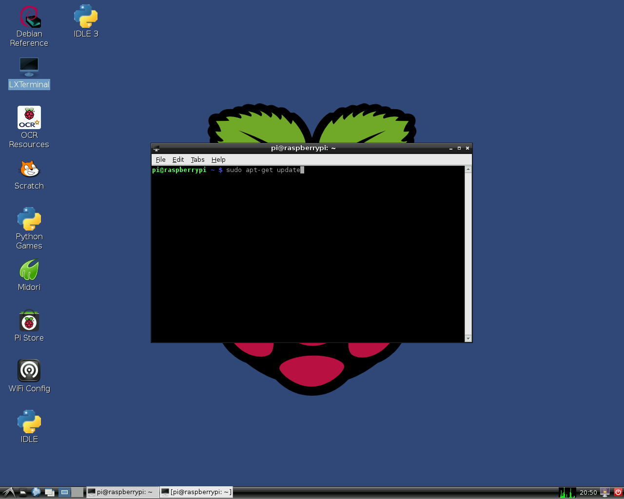
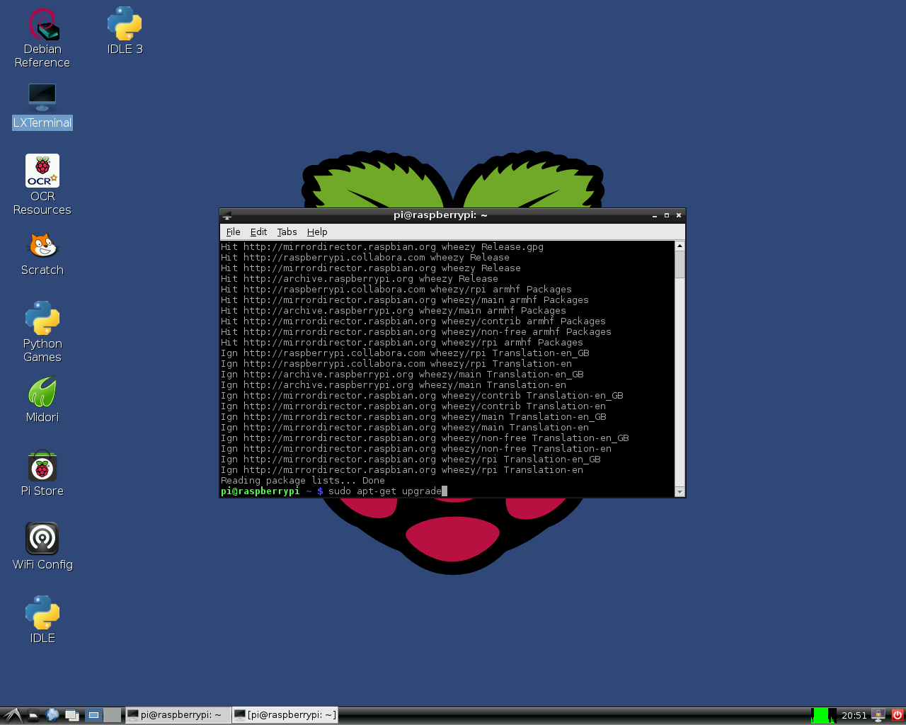
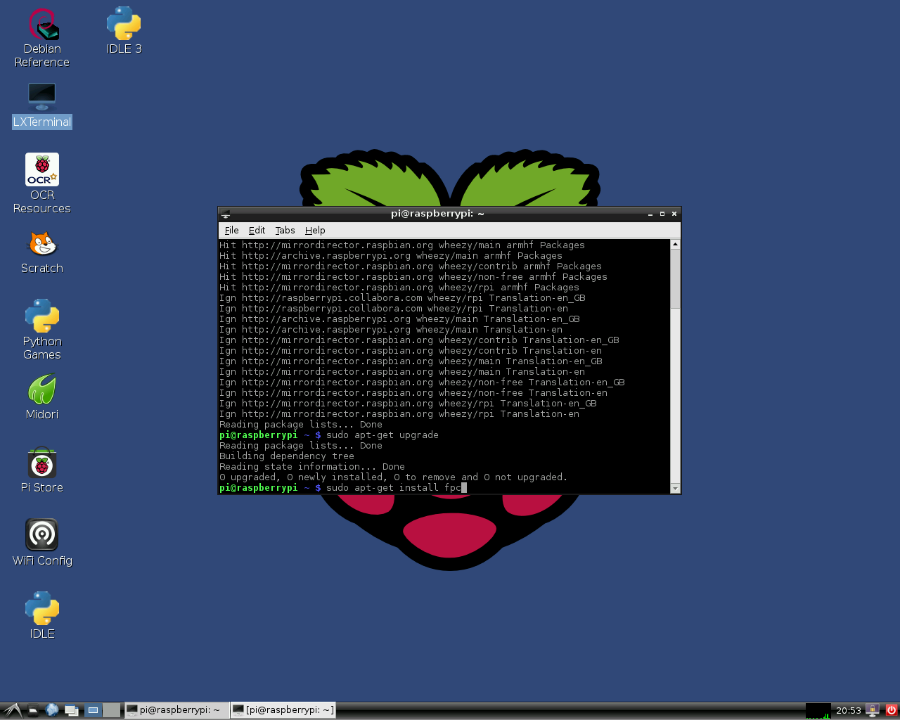
在 Raspbian OS上,安装Lazarus与 Free Pascal很容易。打开命令行窗口输入下面的指令:
sudo apt-get update
sudo apt-get upgrade
sudo apt-get install fpc
sudo apt-get install lazarus
这里安装的是为Raspberry Pi预编译的稳定版FPC与Lazarus 。当然,需要有网络连接。安装过程大概需要30分钟,这个过程是自动完成等的。安装完成以后,你就可以从LXDE的开始菜单的“Programming”启动Lazarus了。
Installation 1
Installation 2
Installation 3

Installation 4


如果你需要一个新的版本,或者抱怨Lazarus 的问题, 点击.
Raspberry Pi 2
自2015六月起,普通的“out of the box”安装方法也适用于安装树莓派2的B型。但是安装时获得的版本是相当旧的。想要获得新版FPC和Lazarus请看链接 相关文章.
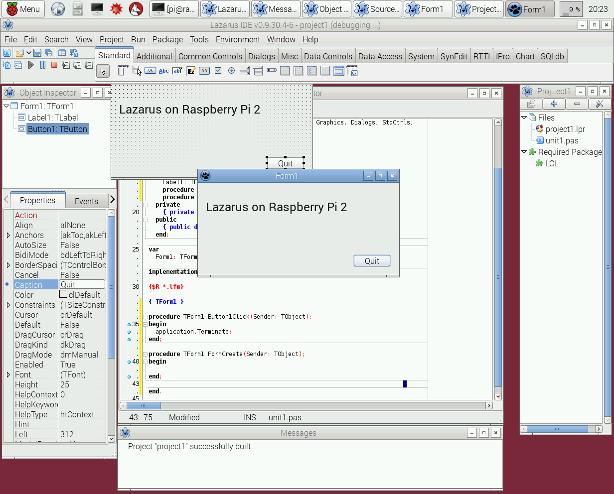
Lazarus "out of the box" on Raspberry Pi 2

Cross compiling for the Raspberry Pi from Windows
从Windows 对Raspberry Pi的交叉编译
1. 使用 fpcup
使用fpcup是实现交叉编译的一种方法,输入下面的指令: fpcup#Linux_ARM_cross_compiler
2. 使用脚本
可以使用手动批处理文件,按照以下步骤。
2.1 先决条件
FPC 2.7.1或更高的安装源代码
下载并安装Windows版本的Linaro binutils for linux gnueabihf到%FPCPATH%/bin/win32-armhf-linux [1]
2.2 创建脚本(需要匹配实际路径)
set PATH=C:\pp\bin\i386-win32;%PATH%;
set FPCMAKEPATH=C:/pp
set FPCPATH=C:/pp
set OUTPATH=C:/pp271
%FPCMAKEPATH%/bin/i386-win32/make distclean OS_TARGET=linux CPU_TARGET=arm  CROSSBINDIR=%FPCPATH%/bin/win32-armhf-linux CROSSOPT="-CpARMV6 -CfVFPV2 -OoFASTMATH" FPC=%FPCPATH%/bin/i386-win32/ppc386.exe

%FPCMAKEPATH%/bin/i386-win32/make all OS_TARGET=linux CPU_TARGET=arm CROSSBINDIR=%FPCPATH%/bin/win32-armhf-linux CROSSOPT="-CpARMV6 -CfVFPV2 -OoFASTMATH" FPC=%FPCPATH%/bin/i386-win32/ppc386.exe
if errorlevel 1 goto quit
%FPCMAKEPATH%/bin/i386-win32/make crossinstall CROSSBINDIR=%FPCPATH%/bin/win32-armhf-linux CROSSOPT="-CpARMV6 -CfVFPV2 -OoFASTMATH" OS_TARGET=linux CPU_TARGET=arm FPC=%FPCPATH%/bin/i386-win32/ppc386.exe INSTALL_BASEDIR=%OUTPATH%

:quit
pause
使用生成的ppcrossarm.exe和 ARM RTL,你可以创建跨平台的Lazarus工程,生成Raspberry Pi和其他armhf设备的应用程序。 注意,这里不包括所有Window 库。
编译源代码
如果你想要从Subversion编译Lazarus源代码。请看 Michell Computing: Lazarus on the Raspberry Pi
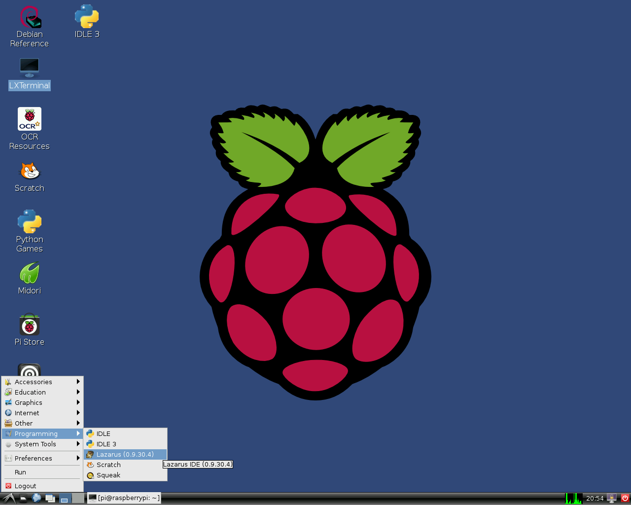
How to start Lazarus in Raspbian Wheezy
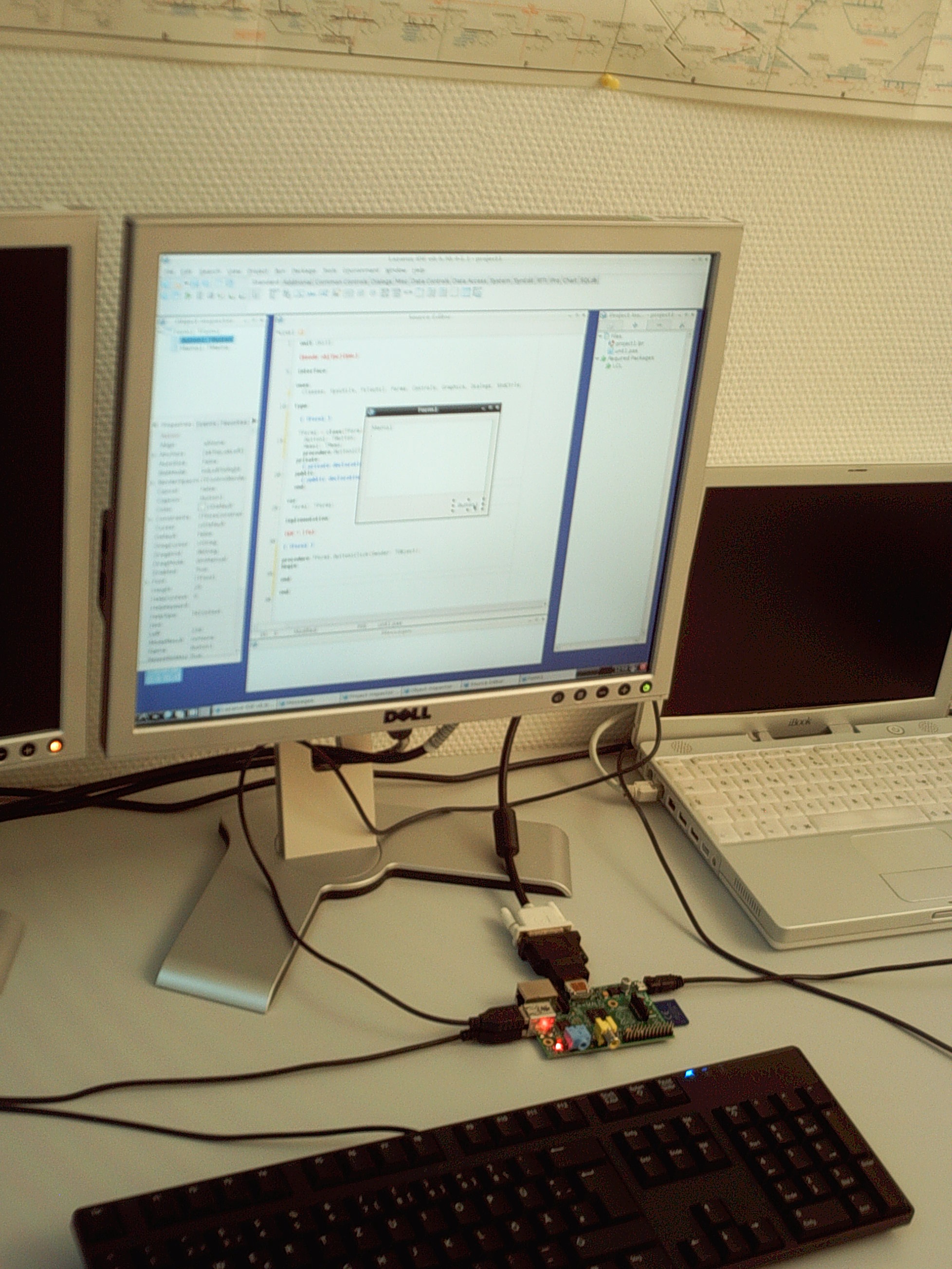
Lazarus on Raspberry Pi
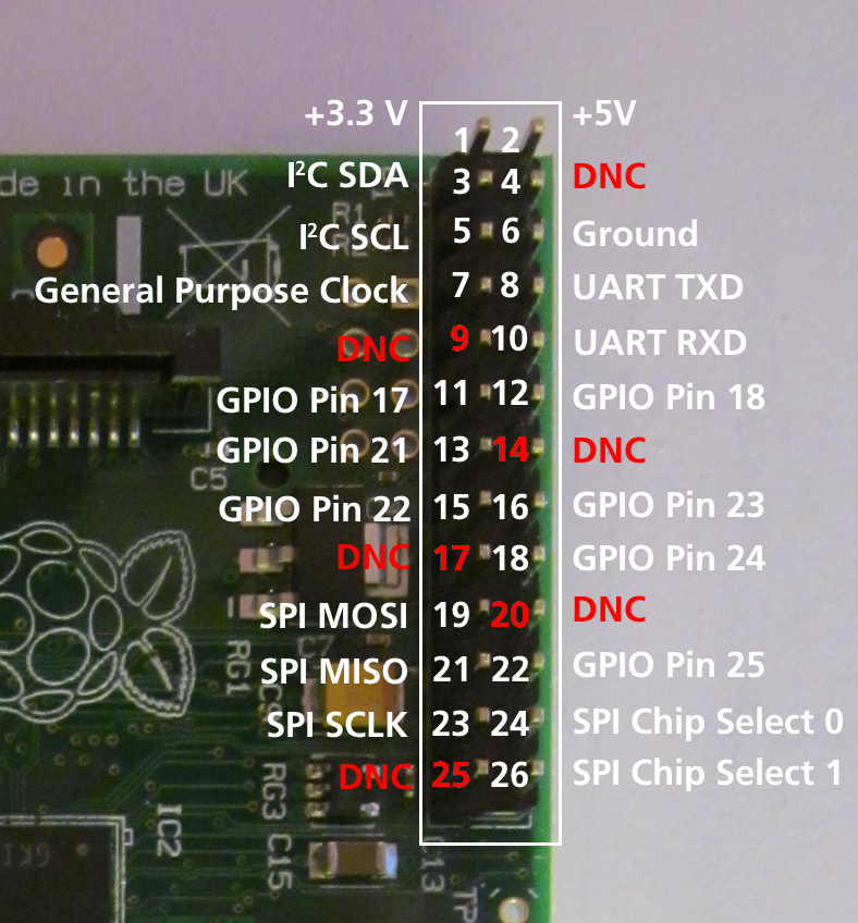
Numbering of GPIO pins


用Gentoo(及其他版本)在Raspberry上编译源码
- Gentoo是一个基于Linux的自由操作系统
如果你想安装最新版的FPC及附件,或者是集成FPC编译器:请阅读下面的指南 这是关于Gentoo的例子,本指南适用其他版本:Install fpc on Raspberry with Gentoo
访问外部硬件

Raspberry Pi的发展的目标之一是方便轻松地访问外部设备,如传感器和控制器。Lazarus有五种方法来访问I/O设备:
- Direct access using the BaseUnix unit
- Access through encapsulated shell calls
- Access through the wiringPi library.
- Access through Unit rpi_hal.
- Access through Unit PiGpio.
- Access through the PascalIO library.
1. Native hardware access


This method provides access to external hardware that doesn't require additional libraries. The only requirement is the BaseUnix library that is part of Free Pascal's RTL.
Switching a device via the GPIO port
The following example lists a simple program that controls the GPIO pin 17 as output to switch an LED, transistor or relais. This program contains a ToggleBox with name GPIO17ToggleBox and for logging return codes a TMemo called LogMemo.
For the example, the anode of a LED has been connected with Pin 11 on the Pi's connector (corresponding to GPIO pin 17 of the BCM2835 SOC) and the LED's cathode was wired via a 68 Ohm resistor to pin 6 of the connector (GND) as previously described by Upton and Halfacree. Subsequently, the LED may be switched on and off with the application's toggle box.
The code requires to be run as root, i.e. either from a root account (not recommended) or via su.
Controlling unit:
unit Unit1;

{Demo application for GPIO on Raspberry Pi}
{Inspired by the Python input/output demo application by Gareth Halfacree}
{written for the Raspberry Pi User Guide, ISBN 978-1-118-46446-5}

{$mode objfpc}{$H+}

interface

uses
  Classes, SysUtils, FileUtil, Forms, Controls, Graphics, Dialogs, StdCtrls,
  Unix, BaseUnix;

type

  { TForm1 }

  TForm1 = class(TForm)
    LogMemo: TMemo;
    GPIO17ToggleBox: TToggleBox;
    procedure FormActivate(Sender: TObject);
    procedure FormClose(Sender: TObject; var CloseAction: TCloseAction);
    procedure GPIO17ToggleBoxChange(Sender: TObject);
  private
    { private declarations }
  public
    { public declarations }
  end;

const
  PIN_17: PChar = '17';
  PIN_ON: PChar = '1';
  PIN_OFF: PChar = '0';
  OUT_DIRECTION: PChar = 'out';

var
  Form1: TForm1;
  gReturnCode: longint; {stores the result of the IO operation}

implementation

{$R *.lfm}

{ TForm1 }

procedure TForm1.FormActivate(Sender: TObject);
var
  fileDesc: integer;
begin
  { Prepare SoC pin 17 (pin 11 on GPIO port) for access: }
  try
    fileDesc := fpopen('/sys/class/gpio/export', O_WrOnly);
    gReturnCode := fpwrite(fileDesc, PIN_17[0], 2);
    LogMemo.Lines.Add(IntToStr(gReturnCode));
  finally
    gReturnCode := fpclose(fileDesc);
    LogMemo.Lines.Add(IntToStr(gReturnCode));
  end;
  { Set SoC pin 17 as output: }
  try
    fileDesc := fpopen('/sys/class/gpio/gpio17/direction', O_WrOnly);
    gReturnCode := fpwrite(fileDesc, OUT_DIRECTION[0], 3);
    LogMemo.Lines.Add(IntToStr(gReturnCode));
  finally
    gReturnCode := fpclose(fileDesc);
    LogMemo.Lines.Add(IntToStr(gReturnCode));
  end;
end;

procedure TForm1.FormClose(Sender: TObject; var CloseAction: TCloseAction);
var
  fileDesc: integer;
begin
  { Free SoC pin 17: }
  try
    fileDesc := fpopen('/sys/class/gpio/unexport', O_WrOnly);
    gReturnCode := fpwrite(fileDesc, PIN_17[0], 2);
    LogMemo.Lines.Add(IntToStr(gReturnCode));
  finally
    gReturnCode := fpclose(fileDesc);
    LogMemo.Lines.Add(IntToStr(gReturnCode));
  end;
end;

procedure TForm1.GPIO17ToggleBoxChange(Sender: TObject);
var
  fileDesc: integer;
begin
  if GPIO17ToggleBox.Checked then
  begin
    { Swith SoC pin 17 on: }
    try
      fileDesc := fpopen('/sys/class/gpio/gpio17/value', O_WrOnly);
      gReturnCode := fpwrite(fileDesc, PIN_ON[0], 1);
      LogMemo.Lines.Add(IntToStr(gReturnCode));
    finally
      gReturnCode := fpclose(fileDesc);
      LogMemo.Lines.Add(IntToStr(gReturnCode));
    end;
  end
  else
  begin
    { Switch SoC pin 17 off: }
    try
      fileDesc := fpopen('/sys/class/gpio/gpio17/value', O_WrOnly);
      gReturnCode := fpwrite(fileDesc, PIN_OFF[0], 1);
      LogMemo.Lines.Add(IntToStr(gReturnCode));
    finally
      gReturnCode := fpclose(fileDesc);
      LogMemo.Lines.Add(IntToStr(gReturnCode));
    end;
  end;
end;

end.
Main program:
program io_test;

{$mode objfpc}{$H+}

uses
  {$IFDEF UNIX}{$IFDEF UseCThreads}
  cthreads,
  {$ENDIF}{$ENDIF}
  Interfaces, // this includes the LCL widgetset
  Forms, Unit1
  { you can add units after this };

{$R *.res}

begin
  Application.Initialize;
  Application.CreateForm(TForm1, Form1);
  Application.Run;
end.
Reading the status of a pin


Of course it is also possible to read the status of e.g. a switch that is connected to the GPIO port.
The following simple example is very similar to the previous one. It controls the GPIO pin 18 as input for a binary device like a switch, transistor or relais. This program contains a CheckBox with name GPIO18CheckBox and for logging return codes a TMemo called LogMemo.
For the example, one pole of a push-button has been connected to Pin 12 on the Pi's connector (corresponding to GPIO pin 18 of the BCM2835 SOC) and via a 10 kOhm pull-up resistor with pin 1 (+3.3V, see wiring diagram). The other pole has been wired to pin 6 of the connector (GND). The program senses the status of the button and correspondingly switches the CheckBox on or off, respectively.
Note that the potential of pin 18 is high if the button is released (by virtue of the connection to pin 1 via the pull-up resistor) and low if it is pressed (since in this situation pin 18 is connected to GND via the switch). Therefore, the GPIO pin signals 0 if the button is pressed and 1 if it is released.
This program has again to be executed as root.
Controlling unit:
unit Unit1;

{Demo application for GPIO on Raspberry Pi}
{Inspired by the Python input/output demo application by Gareth Halfacree}
{written for the Raspberry Pi User Guide, ISBN 978-1-118-46446-5}

{This application reads the status of a push-button}

{$mode objfpc}{$H+}

interface

uses
  Classes, SysUtils, FileUtil, Forms, Controls, Graphics, Dialogs, StdCtrls,
  ButtonPanel, Unix, BaseUnix;

type

  { TForm1 }

  TForm1 = class(TForm)
    ApplicationProperties1: TApplicationProperties;
    GPIO18CheckBox: TCheckBox;
    LogMemo: TMemo;
    procedure ApplicationProperties1Idle(Sender: TObject; var Done: Boolean);
    procedure FormActivate(Sender: TObject);
    procedure FormClose(Sender: TObject; var CloseAction: TCloseAction);
  private
    { private declarations }
  public
    { public declarations }
  end;

const
  PIN_18: PChar = '18';
  IN_DIRECTION: PChar = 'in';

var
  Form1: TForm1;
  gReturnCode: longint; {stores the result of the IO operation}

implementation

{$R *.lfm}

{ TForm1 }

procedure TForm1.FormActivate(Sender: TObject);
var
  fileDesc: integer;
begin
  { Prepare SoC pin 18 (pin 12 on GPIO port) for access: }
  try
    fileDesc := fpopen('/sys/class/gpio/export', O_WrOnly);
    gReturnCode := fpwrite(fileDesc, PIN_18[0], 2);
    LogMemo.Lines.Add(IntToStr(gReturnCode));
  finally
    gReturnCode := fpclose(fileDesc);
    LogMemo.Lines.Add(IntToStr(gReturnCode));
  end;
  { Set SoC pin 18 as input: }
  try
    fileDesc := fpopen('/sys/class/gpio/gpio18/direction', O_WrOnly);
    gReturnCode := fpwrite(fileDesc, IN_DIRECTION[0], 2);
    LogMemo.Lines.Add(IntToStr(gReturnCode));
  finally
    gReturnCode := fpclose(fileDesc);
    LogMemo.Lines.Add(IntToStr(gReturnCode));
  end;
end;

procedure TForm1.ApplicationProperties1Idle(Sender: TObject; var Done: Boolean);
var
  fileDesc: integer;
  buttonStatus: string[1] = '1';
begin
  try
    { Open SoC pin 18 (pin 12 on GPIO port) in read-only mode: }
    fileDesc := fpopen('/sys/class/gpio/gpio18/value', O_RdOnly);
    if fileDesc > 0 then
    begin
      { Read status of this pin (0: button pressed, 1: button released): }
      gReturnCode := fpread(fileDesc, buttonStatus[1], 1);
      LogMemo.Lines.Add(IntToStr(gReturnCode) + ': ' + buttonStatus);
      LogMemo.SelStart := Length(LogMemo.Lines.Text) - 1;
      if buttonStatus = '0' then
        GPIO18CheckBox.Checked := true
      else
        GPIO18CheckBox.Checked := false;
    end;
  finally
    { Close SoC pin 18 (pin 12 on GPIO port) }
    gReturnCode := fpclose(fileDesc);
    LogMemo.Lines.Add(IntToStr(gReturnCode));
    LogMemo.SelStart := Length(LogMemo.Lines.Text) - 1;
  end;
end;

procedure TForm1.FormClose(Sender: TObject; var CloseAction: TCloseAction);
var
  fileDesc: integer;
begin
  { Free SoC pin 18: }
  try
    fileDesc := fpopen('/sys/class/gpio/unexport', O_WrOnly);
    gReturnCode := fpwrite(fileDesc, PIN_18[0], 2);
    LogMemo.Lines.Add(IntToStr(gReturnCode));
  finally
    gReturnCode := fpclose(fileDesc);
    LogMemo.Lines.Add(IntToStr(gReturnCode));
  end;
end;

end.
The main program is identical to that of the example from above.
2. Hardware access via encapsulated shell calls
Another way to access the hardware is by encapsulating terminal commands. This is achieved by using the fpsystem function. This method gives access to functions that are not supported by the BaseUnix unit. The following code implements a program that has the same functionality as the program resulting from the first listing above.
Controlling unit:
unit Unit1;

{Demo application for GPIO on Raspberry Pi}
{Inspired by the Python input/output demo application by Gareth Halfacree}
{written for the Raspberry Pi User Guide, ISBN 978-1-118-46446-5}

{$mode objfpc}{$H+}

interface

uses
  Classes, SysUtils, FileUtil, Forms, Controls, Graphics, Dialogs, StdCtrls, Unix;

type

  { TForm1 }

  TForm1 = class(TForm)
    LogMemo: TMemo;
    GPIO17ToggleBox: TToggleBox;
    procedure FormActivate(Sender: TObject);
    procedure FormClose(Sender: TObject; var CloseAction: TCloseAction);
    procedure GPIO17ToggleBoxChange(Sender: TObject);
  private
    { private declarations }
  public
    { public declarations }
  end;

var
  Form1: TForm1;
  gReturnCode: longint; {stores the result of the IO operation}

implementation

{$R *.lfm}

{ TForm1 }

procedure TForm1.FormActivate(Sender: TObject);
begin
  { Prepare SoC pin 17 (pin 11 on GPIO port) for access: }
  gReturnCode := fpsystem('echo "17" > /sys/class/gpio/export');
  LogMemo.Lines.Add(IntToStr(gReturnCode));
  { Set SoC pin 17 as output: }
  gReturnCode := fpsystem('echo "out" > /sys/class/gpio/gpio17/direction');
  LogMemo.Lines.Add(IntToStr(gReturnCode));
end;

procedure TForm1.FormClose(Sender: TObject; var CloseAction: TCloseAction);
begin
  { Free SoC pin 17: }
  gReturnCode := fpsystem('echo "17" > /sys/class/gpio/unexport');
  LogMemo.Lines.Add(IntToStr(gReturnCode));
end;

procedure TForm1.GPIO17ToggleBoxChange(Sender: TObject);
begin
  if GPIO17ToggleBox.Checked then
  begin
    { Swith SoC pin 17 on: }
    gReturnCode := fpsystem('echo "1" > /sys/class/gpio/gpio17/value');
    LogMemo.Lines.Add(IntToStr(gReturnCode));
  end
  else
  begin
    { Switch SoC pin 17 off: }
    gReturnCode := fpsystem('echo "0" > /sys/class/gpio/gpio17/value');
    LogMemo.Lines.Add(IntToStr(gReturnCode));
  end;
end;

end.
The main program is identical to that of the example above. This program has to be executed with root privileges, too.
3. wiringPi procedures and functions
Alex Schaller's wrapper unit for Gordon Henderson's Arduino compatible wiringPi library provides a numbering scheme that resembles that of Arduino boards.
Function wiringPiSetup:longint: Initializes wiringPi system using the wiringPi pin numbering scheme.
Procedure wiringPiGpioMode(mode:longint): Initializes wiringPi system with the Broadcom GPIO pin numbering scheme.
Procedure pullUpDnControl(pin:longint; pud:longint): controls the internal pull-up/down resistors on a GPIO pin.
Procedure pinMode(pin:longint; mode:longint): sets the mode of a pin to either INPUT, OUTPUT, or PWM_OUTPUT.
Procedure digitalWrite(pin:longint; value:longint): sets an output bit.
Procedure pwmWrite(pin:longint; value:longint): sets an output PWM value between 0 and 1024.
Function digitalRead(pin:longint):longint: reads the value of a given Pin, returning 1 or 0.
Procedure delay(howLong:dword): waits for at least howLong milliseconds.
Procedure delayMicroseconds(howLong:dword): waits for at least howLong microseconds.
Function millis:dword: returns the number of milliseconds since the program called one of the wiringPiSetup functions.
4. rpi_hal-Hardware Abstraction Library (GPIO, I2C and SPI functions and procedures)
This Unit with around 1700 Lines of Code provided by Stefan Fischer, delivers procedures and functions to access the rpi HW I2C, SPI and GPIO:
Just an excerpt of the available functions and procedures:
procedure gpio_set_pin (pin:longword;highlevel:boolean); { Set RPi GPIO pin to high or low level; Speed @ 700MHz -> 0.65MHz }
function gpio_get_PIN (pin:longword):boolean; { Get RPi GPIO pin Level is true when Pin level is '1'; false when '0'; Speed @ 700MHz -> 1.17MHz }
procedure gpio_set_input (pin:longword); { Set RPi GPIO pin to input direction }
procedure gpio_set_output(pin:longword); { Set RPi GPIO pin to output direction }
procedure gpio_set_alt (pin,altfunc:longword); { Set RPi GPIO pin to alternate function nr. 0..5 }
procedure gpio_set_gppud (mask:longword); { set RPi GPIO Pull-up/down Register (GPPUD) with mask }
...
function rpi_snr :string; { delivers SNR: 0000000012345678 }
function rpi_hw :string; { delivers Processor Type: BCM2708 }
function rpi_proc:string; { ARMv6-compatible processor rev 7 (v6l) }
...
function i2c_bus_write(baseadr,reg:word; var data:databuf_t; lgt:byte; testnr:integer) : integer;
function i2c_bus_read (baseadr,reg:word; var data:databuf_t; lgt:byte; testnr:integer) : integer;
function i2c_string_read(baseadr,reg:word; var data:databuf_t; lgt:byte; testnr:integer) : string;
function i2c_string_write(baseadr,reg:word; s:string; testnr:integer) : integer;
...
procedure SPI_Write(devnum:byte; reg,data:word);
function SPI_Read(devnum:byte; reg:word) : byte;
procedure SPI_BurstRead2Buffer (devnum,start_reg:byte; xferlen:longword);
procedure SPI_BurstWriteBuffer (devnum,start_reg:byte; xferlen:longword); { Write 'len' Bytes from Buffer SPI Dev startig at address 'reg' }
...
Test Program (testrpi.pas):
//Simple Test program, which is using rpi_hal;

  program testrpi;
  uses rpi_hal;
  begin
    writeln('Show CPU-Info, RPI-HW-Info and Registers:');
    rpi_show_all_info;
    writeln('Let Status LED Blink. Using GPIO functions:');
    GPIO_PIN_TOGGLE_TEST;
    writeln('Test SPI Read function. (piggy back board with installed RFM22B Module is required!)');
    Test_SPI;
  end.
5. PiGpio Low-level native pascal unit (GPIO control instead of wiringPi c library)
This Unit (pigpio.pas[2]) with 270 Lines of Code provided by Gabor Szollosi, works very fast (for ex. GPIO pin output switching frequency 8 MHz) :
unit PiGpio;
{
 BCM2835 GPIO Registry Driver, also can use to manipulate cpu other registry areas

 This code is tested only Broadcom bcm2835 cpu, different arm cpus may need different
 gpio driver implementation

 2013 Gabor Szollosi
}
{$mode objfpc}{$H+}

interface

uses
  Classes, SysUtils;

const
  REG_GPIO = $20000;//bcm2835 gpio register 0x2000 0000. new fpMap uses page offset, one page is 4096bytes
  // hex 0x1000 so simply calculate 0x2000 0000 / 0x1000  = 0x2000 0
  PAGE_SIZE = 4096;
  BLOCK_SIZE = 4096;
    // The BCM2835 has 54 GPIO pins.
//	BCM2835 data sheet, Page 90 onwards.
//	There are 6 control registers, each control the functions of a block
//	of 10 pins.

  CLOCK_BASE = (REG_GPIO + $101);
  GPIO_BASE =  (REG_GPIO + $200);
  GPIO_PWM =   (REG_GPIO + $20C);

     INPUT = 0;
     OUTPUT = 1;
     PWM_OUTPUT = 2;
     LOW = False;
     HIGH = True;
     PUD_OFF = 0;
     PUD_DOWN = 1;
     PUD_UP = 2;

   // PWM

  PWM_CONTROL = 0;
  PWM_STATUS  = 4;
  PWM0_RANGE  = 16;
  PWM0_DATA   = 20;
  PWM1_RANGE  = 32;
  PWM1_DATA   = 36;

  PWMCLK_CNTL =	160;
  PWMCLK_DIV  =	164;

  PWM1_MS_MODE    = $8000;  // Run in MS mode
  PWM1_USEFIFO    = $2000; // Data from FIFO
  PWM1_REVPOLAR   = $1000;  // Reverse polarity
  PWM1_OFFSTATE   = $0800;  // Ouput Off state
  PWM1_REPEATFF   = $0400;  // Repeat last value if FIFO empty
  PWM1_SERIAL     = $0200;  // Run in serial mode
  PWM1_ENABLE     = $0100;  // Channel Enable

  PWM0_MS_MODE    = $0080;  // Run in MS mode
  PWM0_USEFIFO    = $0020;  // Data from FIFO
  PWM0_REVPOLAR   = $0010;  // Reverse polarity
  PWM0_OFFSTATE   = $0008;  // Ouput Off state
  PWM0_REPEATFF   = $0004;  // Repeat last value if FIFO empty
  PWM0_SERIAL     = $0002;  // Run in serial mode
  PWM0_ENABLE     = $0001;  // Channel Enable


type

  { TIoPort }

  TIoPort = class // IO bank object
  private         //

    //function get_pinDirection(aPin: TGpIoPin): TGpioPinConf;

  public
   FGpio: ^LongWord;
   FClk: ^LongWord;
   FPwm: ^LongWord;
   procedure SetPinMode(gpin, mode: byte);
   function GetBit(gpin : byte):boolean;inline; // gets pin bit}
   procedure ClearBit(gpin : byte);inline;// write pin to 0
   procedure SetBit(gpin : byte);inline;// write pin to 1
   procedure SetPullMode(gpin, mode: byte);
   procedure PwmWrite(gpin : byte; value : LongWord);inline;// write pin to pwm value
  end;

  { TIoDriver }

  TIoDriver = class
  private

  public
    destructor Destroy;override;
    function MapIo:boolean;// creates io memory mapping
    procedure UnmapIoRegisrty(FMap: TIoPort);// close io memory mapping
    function CreatePort(PortGpio, PortClk, PortPwm: LongWord):TIoPort; // create new IO port
  end;

var

    fd: integer;// /dev/mem file handle
procedure delayNanoseconds (howLong : LongWord);


implementation

uses
  baseUnix, Unix;

procedure delayNanoseconds (howLong : LongWord);
var
  sleeper, dummy : timespec;
begin
  sleeper.tv_sec  := 0 ;
  sleeper.tv_nsec := howLong ;
  fpnanosleep (@sleeper,@dummy) ;
end;
{ TIoDriver }
//*******************************************************************************
destructor TIoDriver.Destroy;
begin
  inherited Destroy;
end;
//*******************************************************************************
function TIoDriver.MapIo: boolean;
begin
 Result := True;
 fd := fpopen('/dev/mem', O_RdWr or O_Sync); // Open the master /dev/memory device
  if fd < 0 then
  begin
    Result := False; // unsuccessful memory mapping
  end;
 //
end;
//*******************************************************************************
procedure TIoDriver.UnmapIoRegisrty(FMap:TIoPort);
begin
  if FMap.FGpio <> nil then
 begin
   fpMUnmap(FMap.FGpio,PAGE_SIZE);
   FMap.FGpio := Nil;
 end;
 if FMap.FClk <> nil then
 begin
   fpMUnmap(FMap.FClk,PAGE_SIZE);
   FMap.FClk := Nil;
 end;
 if FMap.FPwm <> nil then
 begin
   fpMUnmap(FMap.FPwm ,PAGE_SIZE);
   FMap.FPwm := Nil;
 end;
end;
//*******************************************************************************
function TIoDriver.CreatePort(PortGpio, PortClk, PortPwm: LongWord): TIoPort;
begin
  Result := TIoPort.Create;// new io port, pascal calls new fpMap, where offst is page sized 4096 bytes!!!
  Result.FGpio := FpMmap(Nil, PAGE_SIZE, PROT_READ or PROT_WRITE, MAP_SHARED, fd, PortGpio); // port config gpio memory
  Result.FClk:= FpMmap(Nil, PAGE_SIZE, PROT_READ or PROT_WRITE, MAP_SHARED, fd, PortClk);; // port clk
  Result.FPwm:= FpMmap(Nil, PAGE_SIZE, PROT_READ or PROT_WRITE, MAP_SHARED, fd, PortPwm);; // port pwm
end;
//*******************************************************************************
procedure TIoPort.SetPinMode(gpin, mode: byte);
var
  fSel, shift, alt : byte;
  gpiof, clkf, pwmf : ^LongWord;
begin
  fSel := (gpin div 10)*4 ;  //Select Gpfsel 0 to 5 register
  shift := (gpin mod 10)*3 ;  //0-9 pin shift
  gpiof := Pointer(LongWord(Self.FGpio)+fSel);
  if (mode = INPUT) then
    gpiof^ := gpiof^ and ($FFFFFFFF - (7 shl shift))  //7 shl shift komplemens - Sets bits to zero = input
  else if (mode = OUTPUT) then
  begin
    gpiof^ := gpiof^ and ($FFFFFFFF - (7 shl shift)) or (1 shl shift);
  end
  else if (mode = PWM_OUTPUT) then
  begin
    Case gpin of
      12,13,40,41,45 : alt:= 4 ;
      18,19          : alt:= 2 ;
      else alt:= 0 ;
    end;
    If alt > 0 then
    begin
      gpiof^ := gpiof^ and ($FFFFFFFF - (7 shl shift)) or (alt shl shift);
      clkf := Pointer(LongWord(Self.FClk)+PWMCLK_CNTL);
      clkf^ := $5A000011 or (1 shl 5) ;                  //stop clock
      delayNanoseconds(200);
      clkf := Pointer(LongWord(Self.FClk)+PWMCLK_DIV);
      clkf^ := $5A000000 or (32 shl 12) ;	// set pwm clock div to 32 (19.2/3 = 600KHz)
      clkf := Pointer(LongWord(Self.FClk)+PWMCLK_CNTL);
      clkf^ := $5A000011 ;                               //start clock
      Self.ClearBit(gpin);
      pwmf := Pointer(LongWord(Self.FPwm)+PWM_CONTROL);
      pwmf^ := 0 ;		 	        // Disable PWM
      delayNanoseconds(200);
      pwmf := Pointer(LongWord(Self.FPwm)+PWM0_RANGE);
      pwmf^ := $400 ;                             //max: 1023
      delayNanoseconds(200);
      pwmf := Pointer(LongWord(Self.FPwm)+PWM1_RANGE);
      pwmf^ := $400 ;                             //max: 1023
      delayNanoseconds(200);
      // Enable PWMs
      pwmf := Pointer(LongWord(Self.FPwm)+PWM0_DATA);
      pwmf^ := 0 ;                                //start value
      pwmf := Pointer(LongWord(Self.FPwm)+PWM1_DATA);
      pwmf^ := 0 ;                                //start value
      pwmf := Pointer(LongWord(Self.FPwm)+PWM_CONTROL);
      pwmf^ := PWM0_ENABLE or PWM1_ENABLE ;
    end;
  end;
end;
//*******************************************************************************
procedure TIoPort.SetBit(gpin : byte);
var
   gpiof : ^LongWord;
begin
  gpiof := Pointer(LongWord(Self.FGpio) + 28 + (gpin shr 5) shl 2);
  gpiof^ := 1 shl gpin;
end;
//*******************************************************************************
procedure TIoPort.ClearBit(gpin : byte);
var
   gpiof : ^LongWord;
begin
  gpiof := Pointer(LongWord(Self.FGpio) + 40 + (gpin shr 5) shl 2);
  gpiof^ := 1 shl gpin;
end;
//*******************************************************************************
function TIoPort.GetBit(gpin : byte):boolean;
var
   gpiof : ^LongWord;
begin
  gpiof := Pointer(LongWord(Self.FGpio) + 52 + (gpin shr 5) shl 2);
  if (gpiof^ and (1 shl gpin)) = 0 then Result := False else Result := True;
end;
//*******************************************************************************
procedure TIoPort.SetPullMode(gpin, mode: byte);
var
   pudf, pudclkf : ^LongWord;
begin
  pudf := Pointer(LongWord(Self.FGpio) + 148 );
  pudf^ := mode;   //mode = 0, 1, 2 :Off, Down, Up
  delayNanoseconds(200);
  pudclkf := Pointer(LongWord(Self.FGpio) + 152 + (gpin shr 5) shl 2);
  pudclkf^ := 1 shl gpin ;
  delayNanoseconds(200);
  pudf^ := 0 ;
  pudclkf^ := 0 ;
end;
//*******************************************************************************
procedure TIoPort.PwmWrite(gpin : byte; value : Longword);
var
   pwmf : ^LongWord;
   port : byte;
begin
  Case gpin of
      12,18,40 : port:= PWM0_DATA ;
      13,19,41,45 : port:= PWM1_DATA ;
      else exit;
  end;
  pwmf := Pointer(LongWord(Self.FPwm) + port);
  pwmf^ := value and $FFFFFBFF; // $400 complemens
end;
//*******************************************************************************
end.
Controlling Lazarus unit:(Project files[3])
unit Unit1;

{Demo application for GPIO on Raspberry Pi}
{Inspired by the Python input/output demo application by Gareth Halfacree}
{written for the Raspberry Pi User Guide, ISBN 978-1-118-46446-5}

{$mode objfpc}{$H+}

interface

uses
  Classes, SysUtils, FileUtil, Forms, Controls, Graphics, Dialogs, StdCtrls,
  ExtCtrls, Unix, PiGpio;

type

  { TForm1 }

  TForm1 = class(TForm)
    GPIO25In: TButton;
    SpeedButton: TButton;
    LogMemo: TMemo;
    GPIO23switch: TToggleBox;
    Timer1: TTimer;
    GPIO18Pwm: TToggleBox;
    Direction: TToggleBox;
    procedure DirectionChange(Sender: TObject);
    procedure GPIO18PwmChange(Sender: TObject);
    procedure GPIO25InClick(Sender: TObject);
    procedure FormActivate(Sender: TObject);
    procedure FormClose(Sender: TObject; var CloseAction: TCloseAction);
    procedure GPIO23switchChange(Sender: TObject);
    procedure SpeedButtonClick(Sender: TObject);
    procedure Timer1Timer(Sender: TObject);
  private
    { private declarations }
  public
    { public declarations }
  end;

const
     INPUT = 0;
     OUTPUT = 1;
     PWM_OUTPUT = 2;
     LOW = False;
     HIGH = True;
     PUD_OFF = 0;
     PUD_DOWN = 1;
     PUD_UP = 2;
 // Convert Raspberry Pi P1 pins (Px) to GPIO port
     P3 = 0;
     P5 = 1;
     P7 = 4;
     P8 = 14;
     P10 = 15;
     P11 = 17;
     P12 = 18;
     P13 = 21;
     P15 = 22;
     P16 = 23;
     P18 = 24;
     P19 = 10;
     P21 = 9;
     P22 = 25;
     P23 = 11;
     P24 = 8;
     P26 = 7;

var
  Form1: TForm1;
  GPIO_Driver: TIoDriver;
  GpF: TIoPort;
  PWM :Boolean;
  i, d : integer;
  Pin,Pout,Ppwm : byte;

implementation

{$R *.lfm}

{ TForm1 }

procedure TForm1.FormActivate(Sender: TObject);
begin
  if not GPIO_Driver.MapIo then
  begin
     LogMemo.Lines.Add('Error mapping gpio registry');
  end
  else
  begin
    GpF := GpIo_Driver.CreatePort(GPIO_BASE, CLOCK_BASE, GPIO_PWM);
  end ;
  Timer1.Enabled:= True;
  Timer1.Interval:= 25;     //25 ms controll interval
  Pin := P22;
  Pout := P16;
  Ppwm := P12;
  i:=1;
  GpF.SetPinMode(Pout,OUTPUT);
  GpF.SetPinMode(Pin,INPUT);
  GpF.SetPullMode(Pin,PUD_Up);    // Input PullUp High level
end;

procedure TForm1.GPIO25InClick(Sender: TObject);
begin
  If GpF.GetBit(Pin) then LogMemo.Lines.Add('In: '+IntToStr(1))
                     else LogMemo.Lines.Add('In: '+IntToStr(0));
end;

procedure TForm1.GPIO18PwmChange(Sender: TObject);
begin
  if GPIO18Pwm.Checked then
  begin
    GpF.SetPinMode(Ppwm,PWM_OUTPUT);
    PWM := True;                          //PWM on
  end
  else
  begin
    GpF.SetPinMode(Ppwm,INPUT);
    PWM := False;                          //PWM off
  end;
end;

procedure TForm1.DirectionChange(Sender: TObject);
begin
  if Direction.Checked then d:=10 else d:=-10;
end;


procedure TForm1.FormClose(Sender: TObject; var CloseAction: TCloseAction);
begin
    GpF.SetPinMode(Ppwm,INPUT);
    GpF.ClearBit(Pout);
    GpIo_Driver.UnmapIoRegisrty(GpF);
end;

procedure TForm1.GPIO23switchChange(Sender: TObject);

Begin
  Timer1.Enabled := False;
  if GPIO23switch.Checked then
  begin
    GpF.SetBit(Pout); //Turn LED on
  end
  else
  begin
    GpF.ClearBit(Pout); //Turn LED off
  end;
  Timer1.Enabled := True;
end;

procedure TForm1.SpeedButtonClick(Sender: TObject);
var
  i,p,k,v: longint;
  ido:TDateTime;
begin
  ido:= Time;
  k:= TimeStampToMSecs(DateTimeToTimeStamp(ido));
  LogMemo.Lines.Add('Start: '+TimeToStr(ido));
  p:=10000000 ;
  For i:=1 to p  do Begin
    GpF.SetBit(P16);
    GpF.ClearBit(P16);
  end;
  ido:= Time;
  v:= TimeStampToMSecs(DateTimeToTimeStamp(ido));
  LogMemo.Lines.Add('Stop: '+TimeToStr(ido)+' Frequency: '+
                                IntToStr(p div (v-k))+' kHz');
end;

procedure TForm1.Timer1Timer(Sender: TObject);
begin
  If PWM then Begin
    If (d > 0) and (i+d < 1024) then begin
          i:=i+d;
          GpF.PwmWrite(Ppwm,i);
    end ;
    If (d < 0) and (i+d > -1) then begin
          i:=i+d;
          GpF.PwmWrite(Ppwm,i);
    end;
  end;
end;


end.
References
- Eben Upton and Gareth Halfacree. Raspberry Pi User Guide. John Wiley and Sons, Chichester 2012, ISBN 111846446X
- B. J. Rao (2013) The Raspberry Pi, Pi Vision and Lazarus/FPC. Blaise Pascal Magazine. 29: 14-21.
External Links
- Raspberry Pi Foundation
- Raspberry Pi Spy: Raspberry Pi tutorials, scripts, help and downloads
- Lazarus wrapper unit for Gordon Henderson's wiringPi C library
- Pin layout of the wiringPi library
- Additional information on Lazarus and Raspberry Pi at eLinux.org
- Getting Started with Pascal on the Pi
- Lazberry Pi: Comprehensive information on Lazarus on the Raspberry Pi computer.
- Stefan Fischer's Lazarus unit rpi_hal.
- Improved Lazarus Unit for fast access to GPIO.