Lazarus on Raspberry Pi/es
│
Deutsch (de) │
English (en) │
español (es) │
suomi (fi) │
中文(中国大陆) (zh_CN) │
La información que viene a continuación es una traducción lo más aproximada posible de la entrada en inglés (con alguna variación allí donde requiera ser más detallada o explicativa) y puede que las que se redacten en los otros idiomas alternativos de esta wiki.
Cada uno que utilice esta información bajo su propio riesgo, puede contener errores. Antes de aplicar los ejemplos asegurarse que la información es aplicable (y se corresponde) con la placa sobre la que se va a trabajar dada la existencia de diferentes modelos en los cuales tanto los pines de conexión como su funcionalidad y voltaje pueden variar. Si no se tiene conocimiento de lo que se está haciendo mejor no aplicarlo.
Por otro lado siempre que se trabaja con dispositivos electrónicos se deben guardar las medidas de seguridad apropiadas dado que un uso indebido de dicho hardware puede conllevar la pérdida de la garantía.
Desde aquí no se dá garantía ni implícita ni explícita sobre el correcto funcionamiento de la información aquí mostrada.
Antes de seguir este tutorial es recomendable tener conocimientos de electrónica (también para conocer los riesgos de manejar tensiones e intensidades), aunque los componentes empleados en los ejemplos son simples.
This article applies to Raspberry Pi only.
See also: Multiplatform Programming Guide
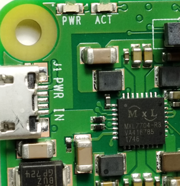
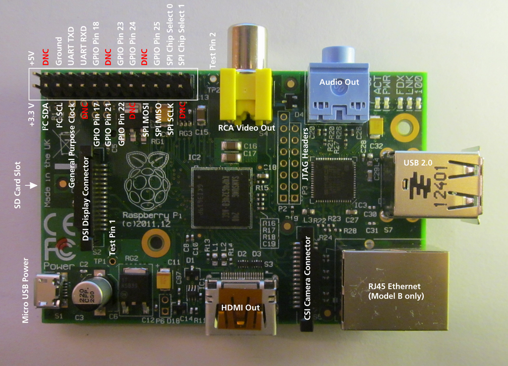
Raspberry Pi es un ordenador con una placa del tamaño de una tarjeta de crédito (ver fotos más abajo). Ha sido diseñada en Reino Unido (UK) por la Fundación Raspberry Pi con la intención de fomentar el aprendizaje básico de la computación en escuelas. Las Raspberry Pi se utilizan también para propósitos tan diversos como pueden ser servidores de medios, robótica e ingeniería de control.
La Fundación Raspberry Pi recomienda Raspbian Wheezy como la distribución estandar a utilizar con su hardware. También se utilizan sistemas alternativos tales como RISC y distribuciones Linux variadas y Android.
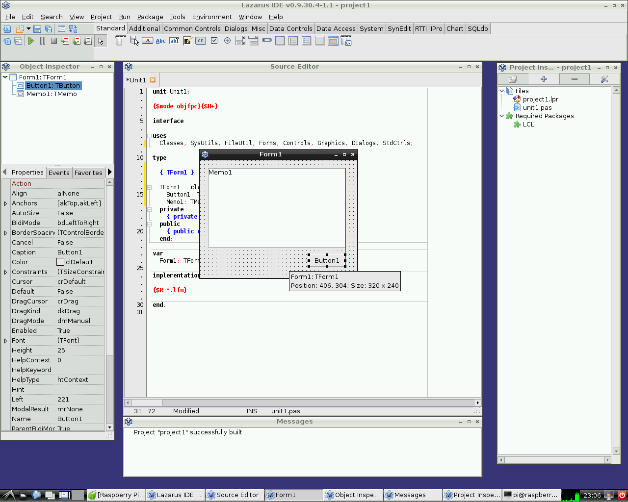
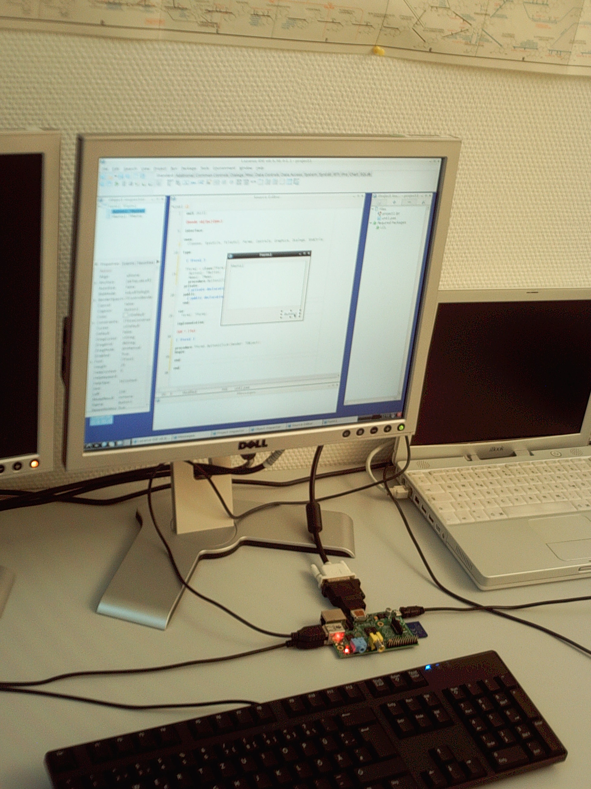
Lazarus corre en modo nativo bajo la distro Raspbian con sistema operativo Linux.
Installando y compilando Lazarus
Instalación simple bajo Raspbian
Raspberry Pi 1
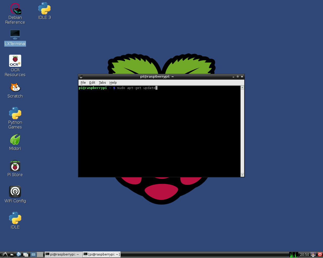
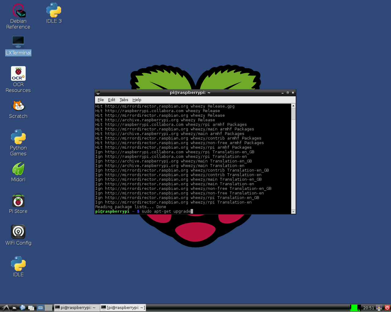
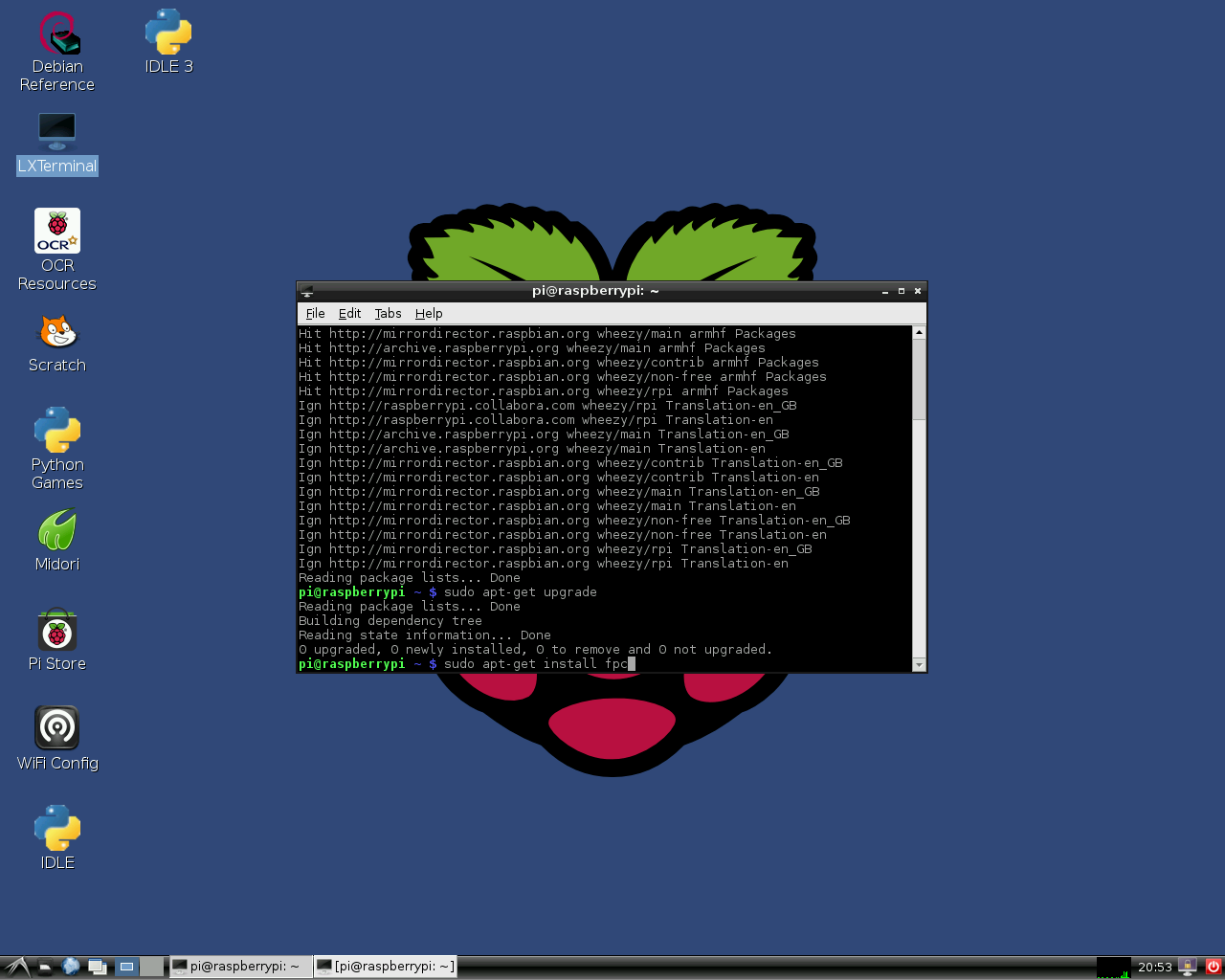
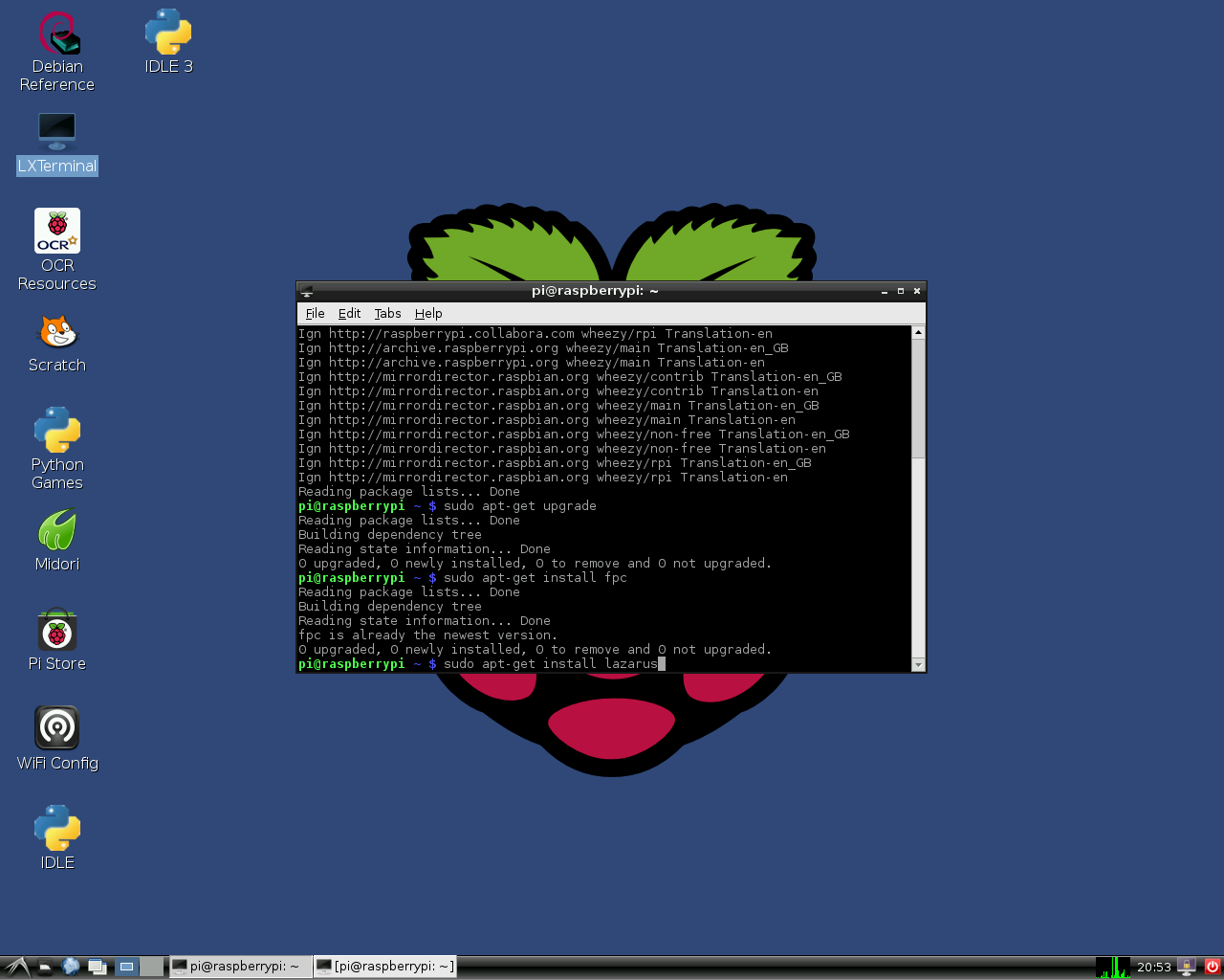
En la distro de Linux Raspbian es fácil instalar Lazarus y FreePascal. Para lograrlo simplemente abre una ventana de terminal y teclea lo siguiente:
sudo apt-get update
sudo apt-get upgrade
sudo apt-get install fpc
sudo apt-get install lazarus
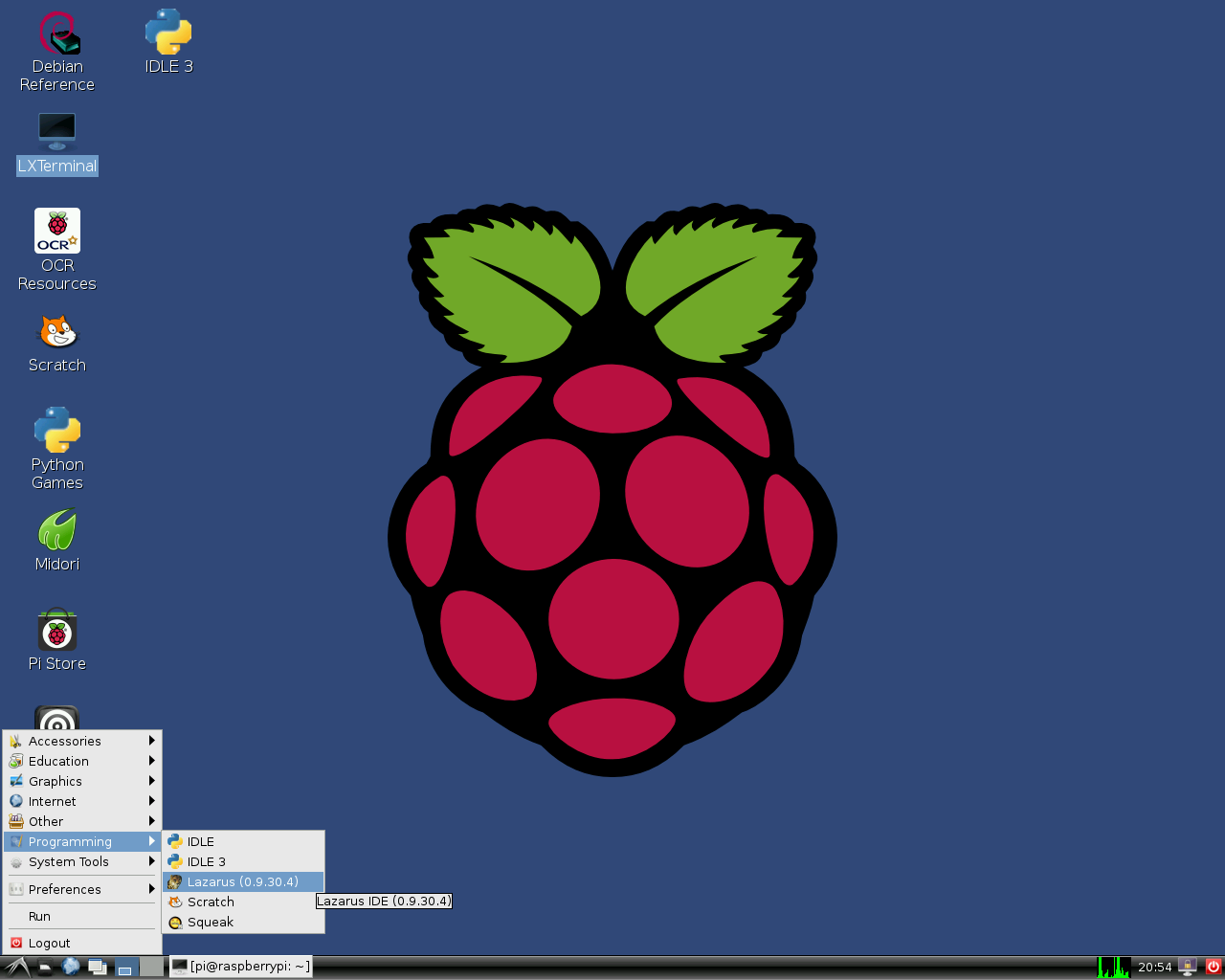
Esto instala una versión precompilada estable de FreePascal y Lazarus en la distro Raspbian que corre en el hardware Raspberry Pi. Por supuesto se necesita una conexión de red. La instalación puede llevar unos 30 minutos, pero la mayor parte de este proceso tiene lugar automáticamente. Después de la instalación ya se puede arrancar Lazarus desde la sección "Programming" en el menú de comienzo de LXDE.
Si necesitas una versión más nueva, o si Lazarus/FreePascal muestran errores durante la instalación puedes consultar más información aquí.
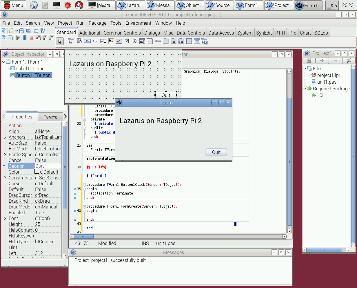
Raspberry Pi 2
Desde junio de 2015 el método de instalación regular "out of the box (listo para usar)" también funciona para Raspberry Pi 2 Modelo B. La versión que lleva instalada es, por tanto, demasiado antigua. Para aquellos que busquen construir los últimos IDE de FreePascal y Lazarus mejor ver este artículo.
160
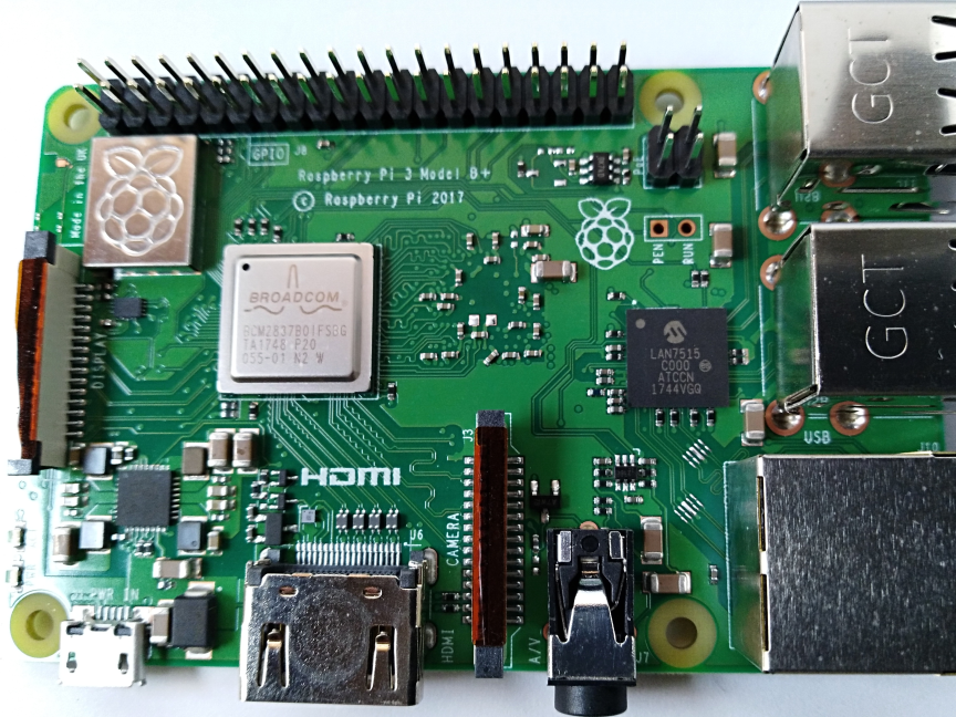
Raspberry Pi 3
Ver Raspberry Pi 2.
Como se puede observar tiene más pines de los cuales se debe consultar la funcionalidad de cada uno antes de conectar algo.
Compilación cruzada (cross compiling) para Raspberry Pi desde Windows
1. Utilizando fpcup
Un camino es utilizar fpcup para configurar un compilador cruzado; seguir estas instrucciones:
fpcup#Linux_ARM_cross_compiler
2. Utilizando scripts
Alternativamente, para una aproximación más manual, y utilizando ficheros de proceso por lotes, puedes seguir los siguientes pasos.
2.1 Prerequisitos
FPC 2.7.1 or higher installed with sourcecode
Install the Windows version from the Linaro binutils for linux gnueabihf into %FPCPATH%/bin/win32-armhf-linux [1]
2.2 Script ejemplo para construir (adaptar los trayectos a como se necesiten)
set PATH=C:\pp\bin\i386-win32;%PATH%;
set FPCMAKEPATH=C:/pp
set FPCPATH=C:/pp
set OUTPATH=C:/pp271
%FPCMAKEPATH%/bin/i386-win32/make distclean OS_TARGET=linux CPU_TARGET=arm  CROSSBINDIR=%FPCPATH%/bin/win32-armhf-linux CROSSOPT="-CpARMV6 -CfVFPV2 -OoFASTMATH" FPC=%FPCPATH%/bin/i386-win32/ppc386.exe

%FPCMAKEPATH%/bin/i386-win32/make all OS_TARGET=linux CPU_TARGET=arm CROSSBINDIR=%FPCPATH%/bin/win32-armhf-linux CROSSOPT="-CpARMV6 -CfVFPV2 -OoFASTMATH" FPC=%FPCPATH%/bin/i386-win32/ppc386.exe
if errorlevel 1 goto quit
%FPCMAKEPATH%/bin/i386-win32/make crossinstall CROSSBINDIR=%FPCPATH%/bin/win32-armhf-linux CROSSOPT="-CpARMV6 -CfVFPV2 -OoFASTMATH" OS_TARGET=linux CPU_TARGET=arm FPC=%FPCPATH%/bin/i386-win32/ppc386.exe INSTALL_BASEDIR=%OUTPATH%

:quit
pause
Con el resultado de ppcrossarm.exe y ARM RTL deberias ser capaz de construir una versión de Lazarus para plataforma cruzada como habitualmente y compilar proyectos FPC para Raspberry Pi y otros dispositivos armhf. Recuerda que no todas las librerias, - especialmente en Windows - se encuentran disponibles para Linux arm.
Compilando desde el código fuente
Puede que necesites compilar Lazarus a partir de sus fuentes subverion. Ver Michell Computing: Lazarus en la Raspberry Pi para más detalles..
Compilando desde las fuentes en Raspberry con Gentoo (y otra distro)
Si necesitas instalar la última release estable de fpc y, adicional y aisladamente, el compilador fpc del trunk entonces puedes leer la siguiente guía.
Esto se escribió utilizando Gentoo, pero esta guía debería ser de utilidad para cualquier otra distro: Install fpc on Raspberry with Gentoo
Accediendo a hardware externo
Una de las finalidades en el desarrollo de Raspberry Pi fue la de facilitar el acceso sin esfuerzo a dispositivos externos tales como sensores y actuadores. A nivel de sofware desde FreePascal y Lazarus además presenta varias modalidades de acceso de E/S (Entrada/Salida) / (I/O (Input/Output):
- Direct access Utilizando la unidad BaseUnix.
- Acceso a través de encapsulated shell calls
- Acceso a través de wiringPi library.
- Acceso a través de la unidad rpi_hal.
- Acceso a través de la unidad PiGpio.
- Acceso a través de la librería PascalIO.
- Acceso a través de la librería PXL.
Acceso nativo al hardware
Este método provee acceso a hardware externo que no requiere librerías adicionales. El único requerimiento es la librería BaseUnix que es parte de la RTL de FreePascal.
Conmutando un dispositivo a través de un puerto GPIO
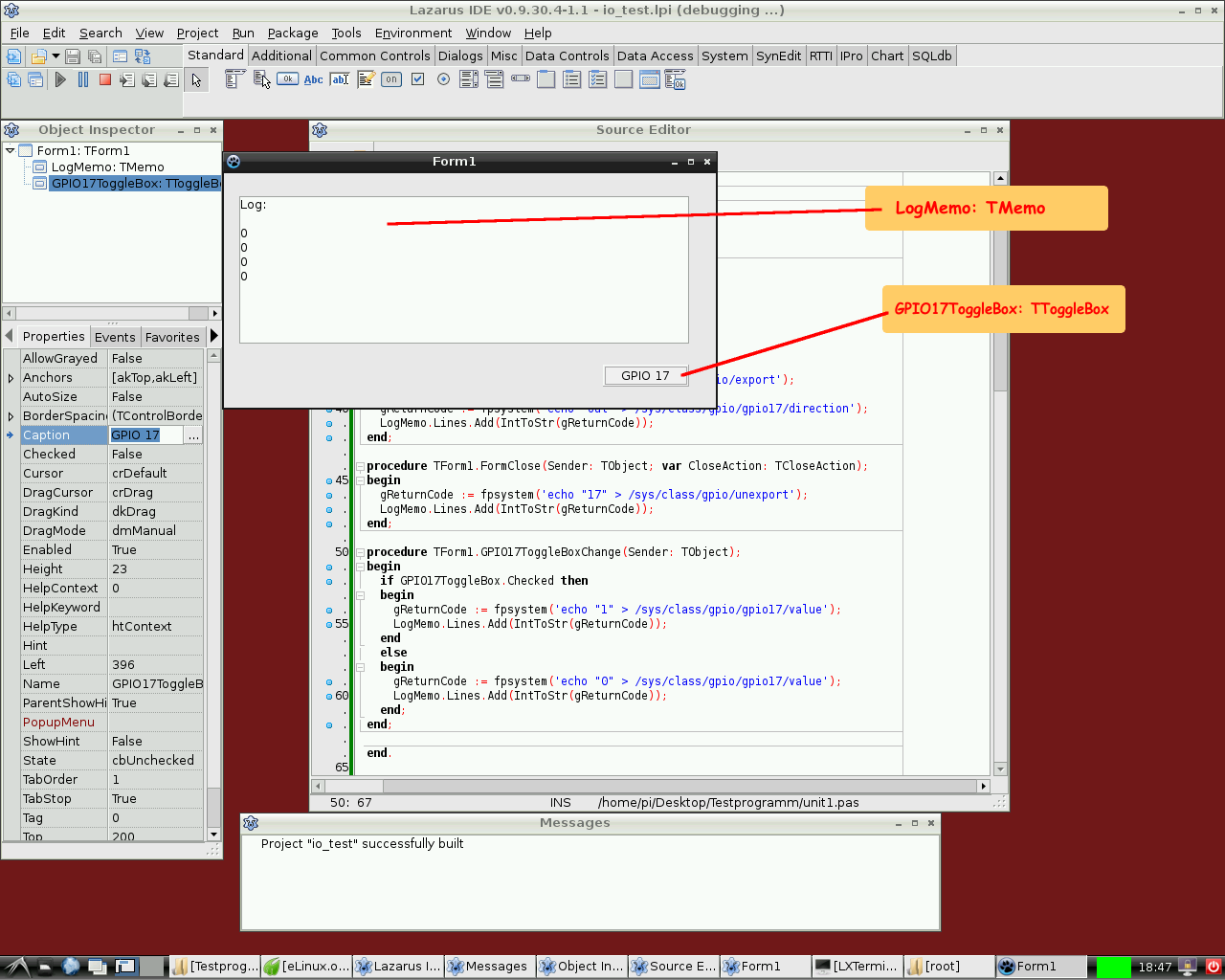
El siguiente ejemplo lista un programa simple que controla el pin 17 GPIO establecido como salida para conmutar el estado de un LED, transistor o relé. Este programa contiene un ToggleBox with name GPIO17ToggleBox y para logging retorna códigos a un TMemo llamado LogMemo.
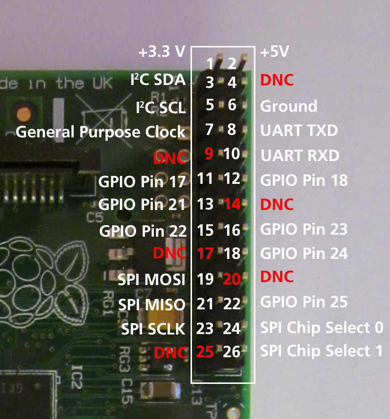
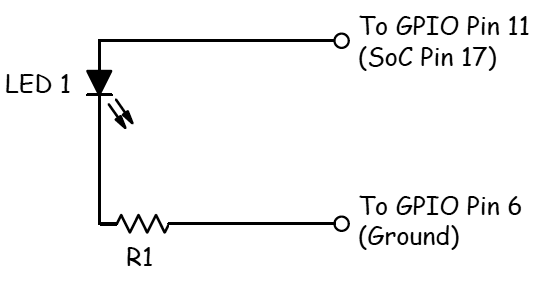
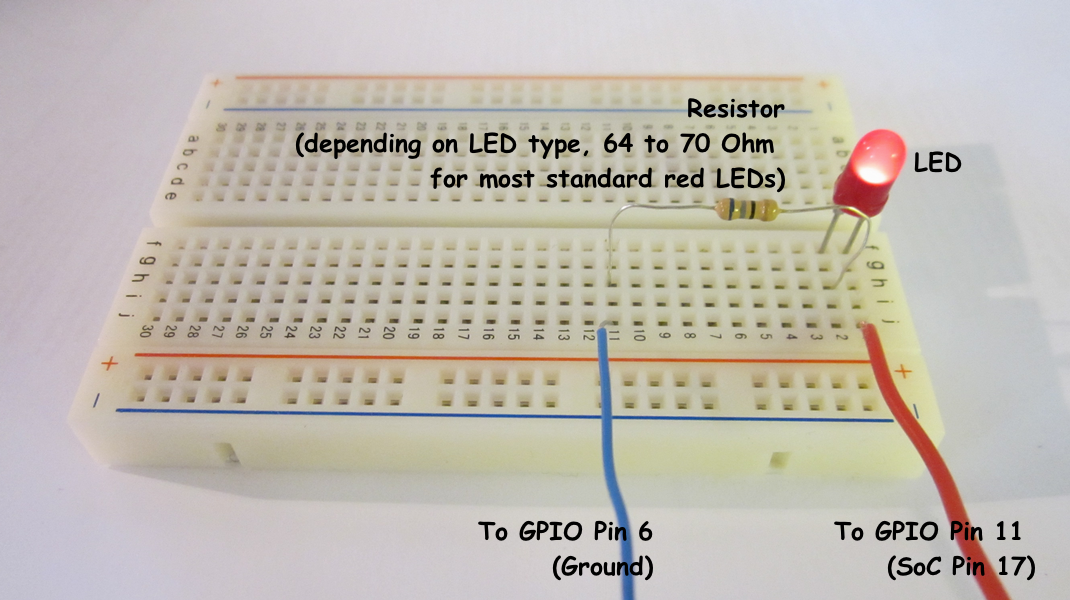
Para el ejemplo, el ánodo del LED se ha conectado al Pin 11 del conector Pi (que a su vez su correspondencia es con el pin 17 del chip BCM2835 SOC) y por otro lado el cátodo del LED se ha conectado al pin 6 del conector (que corresponde a masa (GND: Ground) pero poniendo una resistencia entre medias de 68 Ohm (R1 en el esquema) tal como se describió previamente por Upton and Halfacree (esto nos permite limitar convenientemente la intensidad que circula por el LED). Subsecuentemente el LED puede ser conmutado entre dos estados ON / OFF mediante el toggle box de la aplicación.
El código puede requerir en un principio que se ejecute como root, i.e. adicionalmente con una cuenta tipo root (no recomendado) o a través del mandato su antepuesto al nombre del programa lo que nos promocionará el acceso como super usuario (su: super user). Una mejor opción es añadir el usuario con el que trabajemos a los grupos gpio, i2c y spi tal como se indica a continuación:
sudo adduser pi gpio
sudo adduser pi i2c
sudo adduser pi spi
Unidad de control:
unit Unit1;

{Demo application for GPIO on Raspberry Pi}
{Inspired by the Python input/output demo application by Gareth Halfacree}
{written for the Raspberry Pi User Guide, ISBN 978-1-118-46446-5}

{$mode objfpc}{$H+}

interface

uses
  Classes, SysUtils, FileUtil, Forms, Controls, Graphics, Dialogs, StdCtrls,
  Unix, BaseUnix;

type

  { TForm1 }

  TForm1 = class(TForm)
    LogMemo: TMemo;
    GPIO17ToggleBox: TToggleBox;
    procedure FormActivate(Sender: TObject);
    procedure FormClose(Sender: TObject; var CloseAction: TCloseAction);
    procedure GPIO17ToggleBoxChange(Sender: TObject);
  private
    { private declarations }
  public
    { public declarations }
  end;

const
  PIN_17: PChar = '17';
  PIN_ON: PChar = '1';
  PIN_OFF: PChar = '0';
  OUT_DIRECTION: PChar = 'out';

var
  Form1: TForm1;
  gReturnCode: longint; {stores the result of the IO operation}

implementation

{$R *.lfm}

{ TForm1 }

procedure TForm1.FormActivate(Sender: TObject);
var
  fileDesc: integer;
begin
  { Prepare SoC pin 17 (pin 11 on GPIO port) for access: }
  try
    fileDesc := fpopen('/sys/class/gpio/export', O_WrOnly);
    gReturnCode := fpwrite(fileDesc, PIN_17[0], 2);
    LogMemo.Lines.Add(IntToStr(gReturnCode));
  finally
    gReturnCode := fpclose(fileDesc);
    LogMemo.Lines.Add(IntToStr(gReturnCode));
  end;
  { Set SoC pin 17 as output: }
  try
    fileDesc := fpopen('/sys/class/gpio/gpio17/direction', O_WrOnly);
    gReturnCode := fpwrite(fileDesc, OUT_DIRECTION[0], 3);
    LogMemo.Lines.Add(IntToStr(gReturnCode));
  finally
    gReturnCode := fpclose(fileDesc);
    LogMemo.Lines.Add(IntToStr(gReturnCode));
  end;
end;

procedure TForm1.FormClose(Sender: TObject; var CloseAction: TCloseAction);
var
  fileDesc: integer;
begin
  { Free SoC pin 17: }
  try
    fileDesc := fpopen('/sys/class/gpio/unexport', O_WrOnly);
    gReturnCode := fpwrite(fileDesc, PIN_17[0], 2);
    LogMemo.Lines.Add(IntToStr(gReturnCode));
  finally
    gReturnCode := fpclose(fileDesc);
    LogMemo.Lines.Add(IntToStr(gReturnCode));
  end;
end;

procedure TForm1.GPIO17ToggleBoxChange(Sender: TObject);
var
  fileDesc: integer;
begin
  if GPIO17ToggleBox.Checked then
  begin
    { Swith SoC pin 17 on: }
    try
      fileDesc := fpopen('/sys/class/gpio/gpio17/value', O_WrOnly);
      gReturnCode := fpwrite(fileDesc, PIN_ON[0], 1);
      LogMemo.Lines.Add(IntToStr(gReturnCode));
    finally
      gReturnCode := fpclose(fileDesc);
      LogMemo.Lines.Add(IntToStr(gReturnCode));
    end;
  end
  else
  begin
    { Switch SoC pin 17 off: }
    try
      fileDesc := fpopen('/sys/class/gpio/gpio17/value', O_WrOnly);
      gReturnCode := fpwrite(fileDesc, PIN_OFF[0], 1);
      LogMemo.Lines.Add(IntToStr(gReturnCode));
    finally
      gReturnCode := fpclose(fileDesc);
      LogMemo.Lines.Add(IntToStr(gReturnCode));
    end;
  end;
end;

end.
Programa principal:
program io_test;

{$mode objfpc}{$H+}

uses
  {$IFDEF UNIX}{$IFDEF UseCThreads}
  cthreads,
  {$ENDIF}{$ENDIF}
  Interfaces, // this includes the LCL widgetset
  Forms, Unit1
  { puedes añadir unidades después de esto };

{$R *.res}

begin
  Application.Initialize;
  Application.CreateForm(TForm1, Form1);
  Application.Run;
end.
Leyendo el estado de un pin
Por supuesto también es posible leer el estado de un pulsador conectado a un puerto GPIO (General Porpouse Inpunt Output).
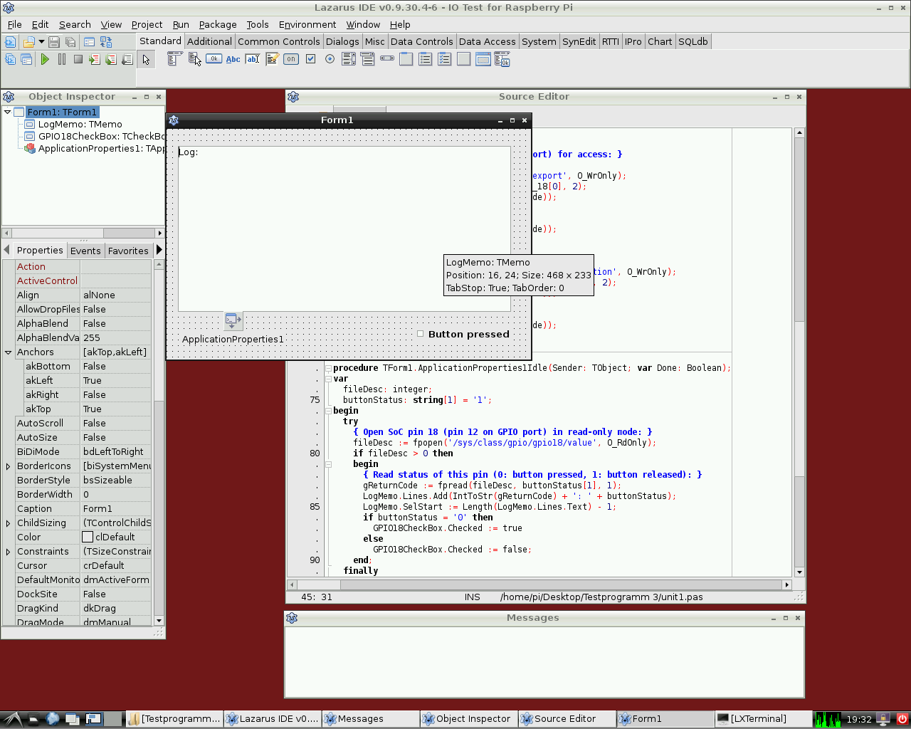
El siguiente ejemplo es muy similar al anterior. Controla el pin GPIO 18 como entrada para un dispositivo binario tal como un pulsador, un transistor o un relé. Este programa contiene un CheckBox con el nombre GPIO18CheckBox y un TMemo llamado LogMemo para los códigos retornados de logging.
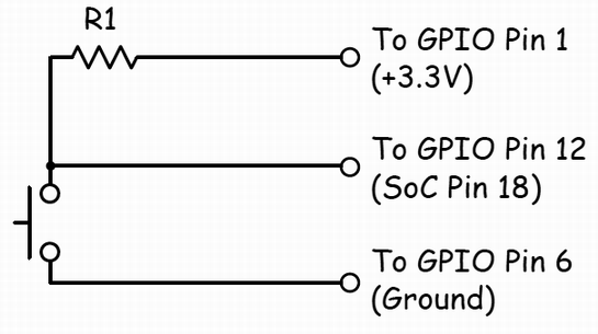
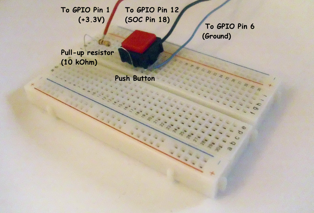
Para el ejemplo se ha conectado un pulsador al Pin 12 del conector de la Pi (correspondiente al pin GPIO 18 del SOC BCM2835) a través de una resistencia de 10 KOhm conectada al pin 1 (+3.3V, ver diagrama de cableado). El otro polo se ha cableado al pin 6 del conector (corresponde a la masa o GND). El programa detecta el estado del pulsador y commuta correlativamente a On u Off según el estado del mismo.
Ten en cuenta que el potencial del pin 18 es "alto" (gracias a la conexión al pin 1 mediate la resistencia) si el pulsador está sin pulsar y "bajo" si se encuentra pulsado (porque en esta situación el pin 18 se encuentra conectado a masa (GND) a través del pulsador). Por tanto, el pin GPIO marca 0 si el botón está presionado y 1 si está sin pulsar.
Este programa tiene que ser ejecutado también como usuario root.
Unidad de control:
unit Unit1;

{Demo application for GPIO on Raspberry Pi}
{Inspired by the Python input/output demo application by Gareth Halfacree}
{written for the Raspberry Pi User Guide, ISBN 978-1-118-46446-5}

{This application reads the status of a push-button}

{$mode objfpc}{$H+}

interface

uses
  Classes, SysUtils, FileUtil, Forms, Controls, Graphics, Dialogs, StdCtrls,
  ButtonPanel, Unix, BaseUnix;

type

  { TForm1 }

  TForm1 = class(TForm)
    ApplicationProperties1: TApplicationProperties;
    GPIO18CheckBox: TCheckBox;
    LogMemo: TMemo;
    procedure ApplicationProperties1Idle(Sender: TObject; var Done: Boolean);
    procedure FormActivate(Sender: TObject);
    procedure FormClose(Sender: TObject; var CloseAction: TCloseAction);
  private
    { private declarations }
  public
    { public declarations }
  end;

const
  PIN_18: PChar = '18';
  IN_DIRECTION: PChar = 'in';

var
  Form1: TForm1;
  gReturnCode: longint; {stores the result of the IO operation}

implementation

{$R *.lfm}

{ TForm1 }

procedure TForm1.FormActivate(Sender: TObject);
var
  fileDesc: integer;
begin
  { Prepare SoC pin 18 (pin 12 on GPIO port) for access: }
  try
    fileDesc := fpopen('/sys/class/gpio/export', O_WrOnly);
    gReturnCode := fpwrite(fileDesc, PIN_18[0], 2);
    LogMemo.Lines.Add(IntToStr(gReturnCode));
  finally
    gReturnCode := fpclose(fileDesc);
    LogMemo.Lines.Add(IntToStr(gReturnCode));
  end;
  { Set SoC pin 18 as input: }
  try
    fileDesc := fpopen('/sys/class/gpio/gpio18/direction', O_WrOnly);
    gReturnCode := fpwrite(fileDesc, IN_DIRECTION[0], 2);
    LogMemo.Lines.Add(IntToStr(gReturnCode));
  finally
    gReturnCode := fpclose(fileDesc);
    LogMemo.Lines.Add(IntToStr(gReturnCode));
  end;
end;

procedure TForm1.ApplicationProperties1Idle(Sender: TObject; var Done: Boolean);
var
  fileDesc: integer;
  buttonStatus: string[1] = '1';
begin
  try
    { Open SoC pin 18 (pin 12 on GPIO port) in read-only mode: }
    fileDesc := fpopen('/sys/class/gpio/gpio18/value', O_RdOnly);
    if fileDesc > 0 then
    begin
      { Read status of this pin (0: button pressed, 1: button released): }
      gReturnCode := fpread(fileDesc, buttonStatus[1], 1);
      LogMemo.Lines.Add(IntToStr(gReturnCode) + ': ' + buttonStatus);
      LogMemo.SelStart := Length(LogMemo.Lines.Text) - 1;
      if buttonStatus = '0' then
        GPIO18CheckBox.Checked := true
      else
        GPIO18CheckBox.Checked := false;
    end;
  finally
    { Close SoC pin 18 (pin 12 on GPIO port) }
    gReturnCode := fpclose(fileDesc);
    LogMemo.Lines.Add(IntToStr(gReturnCode));
    LogMemo.SelStart := Length(LogMemo.Lines.Text) - 1;
  end;
end;

procedure TForm1.FormClose(Sender: TObject; var CloseAction: TCloseAction);
var
  fileDesc: integer;
begin
  { Free SoC pin 18: }
  try
    fileDesc := fpopen('/sys/class/gpio/unexport', O_WrOnly);
    gReturnCode := fpwrite(fileDesc, PIN_18[0], 2);
    LogMemo.Lines.Add(IntToStr(gReturnCode));
  finally
    gReturnCode := fpclose(fileDesc);
    LogMemo.Lines.Add(IntToStr(gReturnCode));
  end;
end;

end.
El programa main es idéntico al del ejemplo de arriba.
Acceso hardware mediante llamadas encapsuladas del shell
Otro modo de acceder al hardware es mediante el encapsulamiento de mandatos a través del shell. Esto se consigue mediante el uso de la función fpsystem. Este método permite el acceso a funciones que no están soportadas por la unidad BaseUnix. El siguiente código implementa un programa que tiene la misma funcionalidad que as the program resulting from the first listing above.
Controlling unit:
unit Unit1;

{Demo application for GPIO on Raspberry Pi}
{Inspired by the Python input/output demo application by Gareth Halfacree}
{written for the Raspberry Pi User Guide, ISBN 978-1-118-46446-5}

{$mode objfpc}{$H+}

interface

uses
  Classes, SysUtils, FileUtil, Forms, Controls, Graphics, Dialogs, StdCtrls, Unix;

type

  { TForm1 }

  TForm1 = class(TForm)
    LogMemo: TMemo;
    GPIO17ToggleBox: TToggleBox;
    procedure FormActivate(Sender: TObject);
    procedure FormClose(Sender: TObject; var CloseAction: TCloseAction);
    procedure GPIO17ToggleBoxChange(Sender: TObject);
  private
    { private declarations }
  public
    { public declarations }
  end;

var
  Form1: TForm1;
  gReturnCode: longint; {stores the result of the IO operation}

implementation

{$R *.lfm}

{ TForm1 }

procedure TForm1.FormActivate(Sender: TObject);
begin
  { Prepare SoC pin 17 (pin 11 on GPIO port) for access: }
  gReturnCode := fpsystem('echo "17" > /sys/class/gpio/export');
  LogMemo.Lines.Add(IntToStr(gReturnCode));
  { Set SoC pin 17 as output: }
  gReturnCode := fpsystem('echo "out" > /sys/class/gpio/gpio17/direction');
  LogMemo.Lines.Add(IntToStr(gReturnCode));
end;

procedure TForm1.FormClose(Sender: TObject; var CloseAction: TCloseAction);
begin
  { Free SoC pin 17: }
  gReturnCode := fpsystem('echo "17" > /sys/class/gpio/unexport');
  LogMemo.Lines.Add(IntToStr(gReturnCode));
end;

procedure TForm1.GPIO17ToggleBoxChange(Sender: TObject);
begin
  if GPIO17ToggleBox.Checked then
  begin
    { Swith SoC pin 17 on: }
    gReturnCode := fpsystem('echo "1" > /sys/class/gpio/gpio17/value');
    LogMemo.Lines.Add(IntToStr(gReturnCode));
  end
  else
  begin
    { Switch SoC pin 17 off: }
    gReturnCode := fpsystem('echo "0" > /sys/class/gpio/gpio17/value');
    LogMemo.Lines.Add(IntToStr(gReturnCode));
  end;
end;

end.
El programa main es idéntico al del ejemplo de arriba. Este programa necesita ejecutarse con privilegios de root también.
Procedimientos y funciones de wiringPi
Alex Schaller's wrapper unit for Gordon Henderson's Arduino compatible wiringPi library provides a numbering scheme that resembles that of Arduino boards.
Function wiringPiSetup:longint: Initializes wiringPi system using the wiringPi pin numbering scheme.
Procedure wiringPiGpioMode(mode:longint): Initializes wiringPi system with the Broadcom GPIO pin numbering scheme.
Procedure pullUpDnControl(pin:longint; pud:longint): controls the internal pull-up/down resistors on a GPIO pin.
Procedure pinMode(pin:longint; mode:longint): sets the mode of a pin to either INPUT, OUTPUT, or PWM_OUTPUT.
Procedure digitalWrite(pin:longint; value:longint): sets an output bit.
Procedure pwmWrite(pin:longint; value:longint): sets an output PWM value between 0 and 1024.
Function digitalRead(pin:longint):longint: reads the value of a given Pin, returning 1 or 0.
Procedure delay(howLong:dword): waits for at least howLong milliseconds.
Procedure delayMicroseconds(howLong:dword): waits for at least howLong microseconds.
Function millis:dword: returns the number of milliseconds since the program called one of the wiringPiSetup functions.
rpi_hal-Hardware Abstraction Library (funciones y procedimientos GPIO, I2C y SPI de la librería de abstracción hardware de la RaspBerry Pi)
Esta unidad con cerca de 1700 líneas de código aportada por Stefan Fischer, aporta procedimientos y funciones para acceso HW I2C, SPI y GPIO en la RaspBerry Pi:
Justamente un extracto de los procedimientos y funciones disponibles:
procedure gpio_set_pin (pin:longword;highlevel:boolean); { Establece RPi GPIO pin a nivel alto o bajo; Velocidad @ 700MHz -> 0.65MHz }
function gpio_get_PIN (pin:longword):boolean; { Get RPi GPIO pin Level is true when Pin level is '1'; false when '0'; Speed @ 700MHz -> 1.17MHz }
procedure gpio_set_input (pin:longword); { Establece RPi GPIO pin en modo entrada }
procedure gpio_set_output(pin:longword); { Establece RPi GPIO pin en modo salida}
procedure gpio_set_alt (pin,altfunc:longword); { Establece RPi GPIO pin to alternate function nr. 0..5 }
procedure gpio_set_gppud (mask:longword); { Establece RPi GPIO Pull-up/down Register (GPPUD) with mask }
...
function rpi_snr :string; { Emtrega el SNR: 0000000012345678 }
function rpi_hw :string; { Entrega el tipo de procesador: BCM2708 }
function rpi_proc:string; { ARMv6-compatible processor rev 7 (v6l) }
...
function i2c_bus_write(baseadr,reg:word; var data:databuf_t; lgt:byte; testnr:integer) : integer;
function i2c_bus_read (baseadr,reg:word; var data:databuf_t; lgt:byte; testnr:integer) : integer;
function i2c_string_read(baseadr,reg:word; var data:databuf_t; lgt:byte; testnr:integer) : string;
function i2c_string_write(baseadr,reg:word; s:string; testnr:integer) : integer;
...
procedure SPI_Write(devnum:byte; reg,data:word);
function SPI_Read(devnum:byte; reg:word) : byte;
procedure SPI_BurstRead2Buffer (devnum,start_reg:byte; xferlen:longword);
procedure SPI_BurstWriteBuffer (devnum,start_reg:byte; xferlen:longword); { Write 'len' Bytes from Buffer SPI Dev startig at address 'reg' }
...
Test Program (testrpi.pas):
//Progama simple de chequeo, el cual utiliza rpi_hal;

  program testrpi;
  uses rpi_hal;
  begin
    writeln('Show CPU-Info, RPI-HW-Info and Registers:');
    rpi_show_all_info;
    writeln('Let Status LED Blink. Using GPIO functions:');
    GPIO_PIN_TOGGLE_TEST;
    writeln('Test SPI Read function. (piggy back board with installed RFM22B Module is required!)');
    Test_SPI;
  end.
Unidad nativa PiGpio de bajo nivel escrita en pascal (control GPIO en lugar de la librería c de wiringPi)
Esta unit (pigpio.pas[2]) de 270 líneas de código aportada por Gabor Szollosi, funciona muy rápido (para ex. GPIO pin output conmutando a una frecuencia de 8 MHz) :
unit PiGpio;
{
 BCM2835 GPIO Registry Driver, also can use to manipulate cpu other registry areas

 This code is tested only Broadcom bcm2835 cpu, different arm cpus may need different
 gpio driver implementation

 2013 Gabor Szollosi
}
{$mode objfpc}{$H+}

interface

uses
  Classes, SysUtils;

const
  REG_GPIO = $3F000;// bcm2835 gpio register 0x2000 0000 (RPi1), 0x3F00 0000 (RPi2)
  // new fpMap uses page offset, one page is 4096 bytes = 0x1000 so simply calculate 0x2000 0000 / 0x1000  = 0x2000 0
  PAGE_SIZE = 4096;
  BLOCK_SIZE = 4096;
  // The BCM2835 has 54 GPIO pins.
  //	BCM2835 data sheet, Page 90 onwards.
  //	There are 6 control registers, each control the functions of a block
  //	of 10 pins.

  CLOCK_BASE = (REG_GPIO + $101);
  GPIO_BASE =  (REG_GPIO + $200);
  GPIO_PWM =   (REG_GPIO + $20C);

     INPUT = 0;
     OUTPUT = 1;
     PWM_OUTPUT = 2;
     LOW = False;
     HIGH = True;
     PUD_OFF = 0;
     PUD_DOWN = 1;
     PUD_UP = 2;

   // PWM

  PWM_CONTROL = 0;
  PWM_STATUS  = 4;
  PWM0_RANGE  = 16;
  PWM0_DATA   = 20;
  PWM1_RANGE  = 32;
  PWM1_DATA   = 36;

  PWMCLK_CNTL =	160;
  PWMCLK_DIV  =	164;

  PWM1_MS_MODE    = $8000;  // Run in MS mode
  PWM1_USEFIFO    = $2000; // Data from FIFO
  PWM1_REVPOLAR   = $1000;  // Reverse polarity
  PWM1_OFFSTATE   = $0800;  // Ouput Off state
  PWM1_REPEATFF   = $0400;  // Repeat last value if FIFO empty
  PWM1_SERIAL     = $0200;  // Run in serial mode
  PWM1_ENABLE     = $0100;  // Channel Enable

  PWM0_MS_MODE    = $0080;  // Run in MS mode
  PWM0_USEFIFO    = $0020;  // Data from FIFO
  PWM0_REVPOLAR   = $0010;  // Reverse polarity
  PWM0_OFFSTATE   = $0008;  // Ouput Off state
  PWM0_REPEATFF   = $0004;  // Repeat last value if FIFO empty
  PWM0_SERIAL     = $0002;  // Run in serial mode
  PWM0_ENABLE     = $0001;  // Channel Enable


type

  { TIoPort }

  TIoPort = class // IO bank object
  private         //

    //function get_pinDirection(aPin: TGpIoPin): TGpioPinConf;

  public
   FGpio: ^LongWord;
   FClk: ^LongWord;
   FPwm: ^LongWord;
   procedure SetPinMode(gpin, mode: byte);
   function GetBit(gpin : byte):boolean;inline; // gets pin bit}
   procedure ClearBit(gpin : byte);inline;// write pin to 0
   procedure SetBit(gpin : byte);inline;// write pin to 1
   procedure SetPullMode(gpin, mode: byte);
   procedure PwmWrite(gpin : byte; value : LongWord);inline;// write pin to pwm value
  end;

  { TIoDriver }

  TIoDriver = class
  private

  public
    destructor Destroy;override;
    function MapIo:boolean;// creates io memory mapping
    procedure UnmapIoRegisrty(FMap: TIoPort);// close io memory mapping
    function CreatePort(PortGpio, PortClk, PortPwm: LongWord):TIoPort; // create new IO port
  end;

var

    fd: integer;// /dev/mem file handle
procedure delayNanoseconds (howLong : LongWord);


implementation

uses
  baseUnix, Unix;

procedure delayNanoseconds (howLong : LongWord);
var
  sleeper, dummy : timespec;
begin
  sleeper.tv_sec  := 0 ;
  sleeper.tv_nsec := howLong ;
  fpnanosleep (@sleeper,@dummy) ;
end;
{ TIoDriver }
//*******************************************************************************
destructor TIoDriver.Destroy;
begin
  inherited Destroy;
end;
//*******************************************************************************
function TIoDriver.MapIo: boolean;
begin
 Result := True;
 fd := fpopen('/dev/mem', O_RdWr or O_Sync); // Open the master /dev/memory device
  if fd < 0 then
  begin
    Result := False; // unsuccessful memory mapping
  end;
 //
end;
//*******************************************************************************
procedure TIoDriver.UnmapIoRegisrty(FMap:TIoPort);
begin
  if FMap.FGpio <> nil then
 begin
   fpMUnmap(FMap.FGpio,PAGE_SIZE);
   FMap.FGpio := Nil;
 end;
 if FMap.FClk <> nil then
 begin
   fpMUnmap(FMap.FClk,PAGE_SIZE);
   FMap.FClk := Nil;
 end;
 if FMap.FPwm <> nil then
 begin
   fpMUnmap(FMap.FPwm ,PAGE_SIZE);
   FMap.FPwm := Nil;
 end;
end;
//*******************************************************************************
function TIoDriver.CreatePort(PortGpio, PortClk, PortPwm: LongWord): TIoPort;
begin
  Result := TIoPort.Create;// new io port, pascal calls new fpMap, where offst is page sized 4096 bytes!!!
  Result.FGpio := FpMmap(Nil, PAGE_SIZE, PROT_READ or PROT_WRITE, MAP_SHARED, fd, PortGpio); // port config gpio memory
  Result.FClk:= FpMmap(Nil, PAGE_SIZE, PROT_READ or PROT_WRITE, MAP_SHARED, fd, PortClk);; // port clk
  Result.FPwm:= FpMmap(Nil, PAGE_SIZE, PROT_READ or PROT_WRITE, MAP_SHARED, fd, PortPwm);; // port pwm
end;
//*******************************************************************************
procedure TIoPort.SetPinMode(gpin, mode: byte);
var
  fSel, shift, alt : byte;
  gpiof, clkf, pwmf : ^LongWord;
begin
  fSel := (gpin div 10)*4 ;  //Select Gpfsel 0 to 5 register
  shift := (gpin mod 10)*3 ;  //0-9 pin shift
  gpiof := Pointer(LongWord(Self.FGpio)+fSel);
  if (mode = INPUT) then
    gpiof^ := gpiof^ and ($FFFFFFFF - (7 shl shift))  //7 shl shift komplemens - Sets bits to zero = input
  else if (mode = OUTPUT) then
  begin
    gpiof^ := gpiof^ and ($FFFFFFFF - (7 shl shift)) or (1 shl shift);
  end
  else if (mode = PWM_OUTPUT) then
  begin
    Case gpin of
      12,13,40,41,45 : alt:= 4 ;
      18,19          : alt:= 2 ;
      else alt:= 0 ;
    end;
    If alt > 0 then
    begin
      gpiof^ := gpiof^ and ($FFFFFFFF - (7 shl shift)) or (alt shl shift);
      clkf := Pointer(LongWord(Self.FClk)+PWMCLK_CNTL);
      clkf^ := $5A000011 or (1 shl 5) ;                  //stop clock
      delayNanoseconds(200);
      clkf := Pointer(LongWord(Self.FClk)+PWMCLK_DIV);
      clkf^ := $5A000000 or (32 shl 12) ;	// set pwm clock div to 32 (19.2/3 = 600KHz)
      clkf := Pointer(LongWord(Self.FClk)+PWMCLK_CNTL);
      clkf^ := $5A000011 ;                               //start clock
      Self.ClearBit(gpin);
      pwmf := Pointer(LongWord(Self.FPwm)+PWM_CONTROL);
      pwmf^ := 0 ;		 	        // Disable PWM
      delayNanoseconds(200);
      pwmf := Pointer(LongWord(Self.FPwm)+PWM0_RANGE);
      pwmf^ := $400 ;                             //max: 1023
      delayNanoseconds(200);
      pwmf := Pointer(LongWord(Self.FPwm)+PWM1_RANGE);
      pwmf^ := $400 ;                             //max: 1023
      delayNanoseconds(200);
      // Enable PWMs
      pwmf := Pointer(LongWord(Self.FPwm)+PWM0_DATA);
      pwmf^ := 0 ;                                //start value
      pwmf := Pointer(LongWord(Self.FPwm)+PWM1_DATA);
      pwmf^ := 0 ;                                //start value
      pwmf := Pointer(LongWord(Self.FPwm)+PWM_CONTROL);
      pwmf^ := PWM0_ENABLE or PWM1_ENABLE ;
    end;
  end;
end;
//*******************************************************************************
procedure TIoPort.SetBit(gpin : byte);
var
   gpiof : ^LongWord;
begin
  gpiof := Pointer(LongWord(Self.FGpio) + 28 + (gpin shr 5) shl 2);
  gpiof^ := 1 shl gpin;
end;
//*******************************************************************************
procedure TIoPort.ClearBit(gpin : byte);
var
   gpiof : ^LongWord;
begin
  gpiof := Pointer(LongWord(Self.FGpio) + 40 + (gpin shr 5) shl 2);
  gpiof^ := 1 shl gpin;
end;
//*******************************************************************************
function TIoPort.GetBit(gpin : byte):boolean;
var
   gpiof : ^LongWord;
begin
  gpiof := Pointer(LongWord(Self.FGpio) + 52 + (gpin shr 5) shl 2);
  if (gpiof^ and (1 shl gpin)) = 0 then Result := False else Result := True;
end;
//*******************************************************************************
procedure TIoPort.SetPullMode(gpin, mode: byte);
var
   pudf, pudclkf : ^LongWord;
begin
  pudf := Pointer(LongWord(Self.FGpio) + 148 );
  pudf^ := mode;   //mode = 0, 1, 2 :Off, Down, Up
  delayNanoseconds(200);
  pudclkf := Pointer(LongWord(Self.FGpio) + 152 + (gpin shr 5) shl 2);
  pudclkf^ := 1 shl gpin ;
  delayNanoseconds(200);
  pudf^ := 0 ;
  pudclkf^ := 0 ;
end;
//*******************************************************************************
procedure TIoPort.PwmWrite(gpin : byte; value : Longword);
var
   pwmf : ^LongWord;
   port : byte;
begin
  Case gpin of
      12,18,40 : port:= PWM0_DATA ;
      13,19,41,45 : port:= PWM1_DATA ;
      else exit;
  end;
  pwmf := Pointer(LongWord(Self.FPwm) + port);
  pwmf^ := value and $FFFFFBFF; // $400 complemens
end;
//*******************************************************************************
end.
Controlling Lazarus unit:(Project files[3])
unit Unit1;

{Demo application for GPIO on Raspberry Pi}
{Inspired by the Python input/output demo application by Gareth Halfacree}
{written for the Raspberry Pi User Guide, ISBN 978-1-118-46446-5}

{$mode objfpc}{$H+}

interface

uses
  Classes, SysUtils, FileUtil, Forms, Controls, Graphics, Dialogs, StdCtrls,
  ExtCtrls, Unix, PiGpio;

type

  { TForm1 }

  TForm1 = class(TForm)
    GPIO25In: TButton;
    SpeedButton: TButton;
    LogMemo: TMemo;
    GPIO23switch: TToggleBox;
    Timer1: TTimer;
    GPIO18Pwm: TToggleBox;
    Direction: TToggleBox;
    procedure DirectionChange(Sender: TObject);
    procedure GPIO18PwmChange(Sender: TObject);
    procedure GPIO25InClick(Sender: TObject);
    procedure FormActivate(Sender: TObject);
    procedure FormClose(Sender: TObject; var CloseAction: TCloseAction);
    procedure GPIO23switchChange(Sender: TObject);
    procedure SpeedButtonClick(Sender: TObject);
    procedure Timer1Timer(Sender: TObject);
  private
    { private declarations }
  public
    { public declarations }
  end;

const
     INPUT = 0;
     OUTPUT = 1;
     PWM_OUTPUT = 2;
     LOW = False;
     HIGH = True;
     PUD_OFF = 0;
     PUD_DOWN = 1;
     PUD_UP = 2;
 // Convert Raspberry Pi P1 pins (Px) to GPIO port
     P3 = 0;
     P5 = 1;
     P7 = 4;
     P8 = 14;
     P10 = 15;
     P11 = 17;
     P12 = 18;
     P13 = 21;
     P15 = 22;
     P16 = 23;
     P18 = 24;
     P19 = 10;
     P21 = 9;
     P22 = 25;
     P23 = 11;
     P24 = 8;
     P26 = 7;

var
  Form1: TForm1;
  GPIO_Driver: TIoDriver;
  GpF: TIoPort;
  PWM :Boolean;
  i, d : integer;
  Pin,Pout,Ppwm : byte;

implementation

{$R *.lfm}

{ TForm1 }

procedure TForm1.FormActivate(Sender: TObject);
begin
  if not GPIO_Driver.MapIo then
  begin
     LogMemo.Lines.Add('Error mapping gpio registry');
  end
  else
  begin
    GpF := GpIo_Driver.CreatePort(GPIO_BASE, CLOCK_BASE, GPIO_PWM);
  end ;
  Timer1.Enabled:= True;
  Timer1.Interval:= 25;     //25 ms controll interval
  Pin := P22;
  Pout := P16;
  Ppwm := P12;
  i:=1;
  GpF.SetPinMode(Pout,OUTPUT);
  GpF.SetPinMode(Pin,INPUT);
  GpF.SetPullMode(Pin,PUD_Up);    // Input PullUp High level
end;

procedure TForm1.GPIO25InClick(Sender: TObject);
begin
  If GpF.GetBit(Pin) then LogMemo.Lines.Add('In: '+IntToStr(1))
                     else LogMemo.Lines.Add('In: '+IntToStr(0));
end;

procedure TForm1.GPIO18PwmChange(Sender: TObject);
begin
  if GPIO18Pwm.Checked then
  begin
    GpF.SetPinMode(Ppwm,PWM_OUTPUT);
    PWM := True;                          //PWM on
  end
  else
  begin
    GpF.SetPinMode(Ppwm,INPUT);
    PWM := False;                          //PWM off
  end;
end;

procedure TForm1.DirectionChange(Sender: TObject);
begin
  if Direction.Checked then d:=10 else d:=-10;
end;


procedure TForm1.FormClose(Sender: TObject; var CloseAction: TCloseAction);
begin
    GpF.SetPinMode(Ppwm,INPUT);
    GpF.ClearBit(Pout);
    GpIo_Driver.UnmapIoRegisrty(GpF);
end;

procedure TForm1.GPIO23switchChange(Sender: TObject);

Begin
  Timer1.Enabled := False;
  if GPIO23switch.Checked then
  begin
    GpF.SetBit(Pout); //Turn LED on
  end
  else
  begin
    GpF.ClearBit(Pout); //Turn LED off
  end;
  Timer1.Enabled := True;
end;

procedure TForm1.SpeedButtonClick(Sender: TObject);
var
  i,p,k,v: longint;
  ido:TDateTime;
begin
  ido:= Time;
  k:= TimeStampToMSecs(DateTimeToTimeStamp(ido));
  LogMemo.Lines.Add('Start: '+TimeToStr(ido));
  p:=10000000 ;
  For i:=1 to p  do Begin
    GpF.SetBit(P16);
    GpF.ClearBit(P16);
  end;
  ido:= Time;
  v:= TimeStampToMSecs(DateTimeToTimeStamp(ido));
  LogMemo.Lines.Add('Stop: '+TimeToStr(ido)+' Frequency: '+
                                IntToStr(p div (v-k))+' kHz');
end;

procedure TForm1.Timer1Timer(Sender: TObject);
begin
  If PWM then Begin
    If (d > 0) and (i+d < 1024) then begin
          i:=i+d;
          GpF.PwmWrite(Ppwm,i);
    end ;
    If (d < 0) and (i+d > -1) then begin
          i:=i+d;
          GpF.PwmWrite(Ppwm,i);
    end;
  end;
end;


end.
PXL (Platform eXtended Library) for low level native access to GPIO, I²C, SPI, PWM, UART, V4L2, displays and sensors
- Fácil y rápido acceso a GPIO, I²C, SPI, PWM, UART y timer de alta preción de la CPU.
- V4L2 captura de video/imagen utilizando los conectores dedicados de la placa y cámaras USB. Por ejemplo cámaras serie como VC0706 y LSY201.
- OpenGL ES hardware de renderizado con y sin servidor X. Software de renderizado.
- Pantallas I²C y SPI tales como SSD1306, SSD1351, PCB8544 (Nokia), HX8357 y ILI9340.
- LCD de caracteres con cableado de pines directo.
- Suporte para software SPI y UART (bit-banging).
- Suporte para SC16IS7x0 (controladora UART conectada a través de I²C o SPI), incluyendo pins GPIO extra.
- Soporte para sensores tales como BMP180, DHT22, L3GD20, LSM303 y SHT10.
- Otras características como networking, math, transformación de imágenes, efectos, dibujo de primitivas gráficas...
Más información y descargas de la librería PXL.
Referencias
- Eben Upton and Gareth Halfacree. Raspberry Pi User Guide. John Wiley and Sons, Chichester 2012, ISBN 111846446X
- B. J. Rao (2013) The Raspberry Pi, Pi Vision and Lazarus/FPC. Blaise Pascal Magazine. 29: 14-21.
External Links
- Raspberry Pi Foundation
- Raspberry Pi Spy: Raspberry Pi tutorials, scripts, help and downloads
- Lazarus wrapper unit for Gordon Henderson's wiringPi C library
- Pin layout of the wiringPi library
- Additional information on Lazarus and Raspberry Pi at eLinux.org
- Getting Started with Pascal on the Pi
- Lazberry Pi: Comprehensive information on Lazarus on the Raspberry Pi computer.
- Stefan Fischer's Lazarus unit rpi_hal.
- Improved Lazarus Unit for fast access to GPIO.
- PXL - Platform eXtended Library.
