OpenGL Tutorial/zh CN
│
Deutsch (de) │
English (en) │
español (es) │
français (fr) │
日本語 (ja) │
한국어 (ko) │
русский (ru) │
中文(中国大陆) (zh_CN) │
OpenGL 是开发可移植的交互式2D和3D图形应用的首选环境。自从1992年问世以来,OpenGL已成为业内最广泛使用和最广为支持的2D和3D图形应用编程接口(API),为各种计算平台带来成千的应用。OpenGL通过包含一系列渲染,纹理映射,特殊效果和其他强大的视觉功能极大促进了创新并加速应用开发。开发人员可以在各种主流桌面及工作站平台发挥OpenGL的强大功能确保广泛部署。
在以下联接您会得到更多关于OpenGl信息。here.
GLUT
GLUT (pronounced like the glut in gluttony) 全称 OpenGL Utility Toolkit, 写OpenGL 程序的窗口系统独立工具包。 它实现了一个简单的OpenGL窗口的应用程序编程接口(API). GLUT 让OpenGL编程更加容易理解,GLUT 具有可移植性,可以在不同平台编译。
你能得到更多关于 GLUT的信息: here.
许多系统已预安装了GLUT,但如果你的系统没有的话你可以轻松用Google搜索到 Google.
编译好的Windows可执行文件可在这里找到 www.xmission.com.
GLUT FPC 单元信息在这里 OpenGL.
LCL
Lzazrus组件库也可以使用OpenGL。Lazarus包含了一个OpenGL的LCL控件TOpenGLControl。Lazarus包的位置:lazarus/components/opengl/lazopenglcontext.lpk。有一个实例是:lazarus/examples/openglcontrol/openglcontrol_demo.lpi。
LCL / GLUT
你应该使用GLUT还是LCL?
- 如果你想自己画所有的东西,GLUT会更好。
- 一般应用的话LCL更好。例如一个3D编辑器需要亦歌OpenGL窗口和剩余的一般应用如使用一般的按钮,组合框,窗口,窗口模块等。
OpenGL部分大致相同。 在windows下GLUT需要一个dll(动态链接库) , where LCL typically runs out of the box, but a LCL executable is bigger.
建立您的首个 GLUT 程序
为了使用GLUT,您必须首先初始化它。这可以用glutInit函数完成。该函数可处理主窗体的命令行和设置其参数,但需要使用C/C++风格的输入。您需要编写自己的函数来完成从ParamCount 和 ParamStr 到C/C++风格命令行参数的转换。
 procedure glutInitPascal(ParseCmdLine: Boolean);
 var
   Cmd: array of PChar;
   CmdCount, I: Integer;
 begin
   if ParseCmdLine then
     CmdCount := ParamCount + 1
   else
     CmdCount := 1;
   SetLength(Cmd, CmdCount);
   for I := 0 to CmdCount - 1 do
     Cmd[I] := PChar(ParamStr(I));
   glutInit(@CmdCount, @Cmd);
 end;
本质上,您创建一个数组,并用来自ParamStr的字符串填充。该函数也接受可控制传递到glutInit的参数,无论是整个命令行或仅仅是可执行文件名
ToDo: probably glutInit(@argc, @argv); is enough.
更多有关 glutInit 函数: http://www.opengl.org/resources/libraries/glut/spec3/node10.html
下一步,您需要创建主窗体 使用glutInitDisplayMode设置主窗体显示模式。该函数只接受一个标志位组合为参数。通常您只需要GLUT_DOUBLE 或 GLUT_RGB 或 GLUT_DEPTH 。
更多关于 glutInitDisplayMode 参见: http://www.opengl.org/resources/libraries/glut/spec3/node12.html
窗体位置和大小使用glutInitWindowPosition 和 glutInitWindowSize来控制。他们接受2个参数。前一个参数是X和Y坐标,后一个是宽度和长度。您可使用glutGet以返回窗体大小和中心。
更多关于 glutInitWindowPosition, glutInitWindowSize 和 glutGet: http://www.opengl.org/resources/libraries/glut/spec3/node11.html http://www.opengl.org/documentation/specs/glut/spec3/node70.html
最后,窗体应该采用glutCreateWindow创建。该函数将创建窗体并通过一参数设置其标题。因此它将返回该窗体的句柄。句柄可在其他需要该句柄的函数中使用。
更多关于 glutCreateWindow: http://www.opengl.org/resources/libraries/glut/spec3/node16.html
在您的程序进入主循环前,您必须设置些回调。您需要一个回调来画窗体,改变窗体尺寸及获取键盘输入。这些回调使用glutDisplayFunc, glutReshapeFunc 和 glutKeyboardFunc来设置。
更多有关设置回调,请参见: http://www.opengl.org/resources/libraries/glut/spec3/node45.html#SECTION00080000000000000000
您的绘图函数可能看起来像这样子:
procedure DrawGLScene; cdecl;
begin
  glClear(GL_COLOR_BUFFER_BIT or GL_DEPTH_BUFFER_BIT);
  glutSwapBuffers;
end;
这只能清空窗体为背景色并复位zbuffer。(别担心不懂zbuffer... 更多内容讲解在后面)
您的窗体大小调整函数可能像这样:
procedure ReSizeGLScene(Width, Height: Integer); cdecl;
begin
  if Height = 0 then
    Height := 1;

  glViewport(0, 0, Width, Height);
  glMatrixMode(GL_PROJECTION);
  glLoadIdentity;
  gluPerspective(45, Width / Height, 0.1, 1000);

  glMatrixMode(GL_MODELVIEW);
  glLoadIdentity;
end;
这个代码告诉OpenGL窗体应该绘制在哪里,并且将矩阵设为期望值。(矩阵函数将会在后面介绍)
键盘输入使用以下回调执行:
procedure GLKeyboard(Key: Byte; X, Y: Longint); cdecl;
begin
  if Key = 27 then
    Halt(0);
end;
该函数将告诉您的程序,若是按下ESC键就推出。GLUT为事件驱动,终止您程序的唯一方式就是调用您的回调函数中的Halt。若您以其他方式关闭窗体,窗体是消失了,但程序仍然会在主过程内继续无限地循环。
要启动主循环,调用glutMainLoop.这将进入调用您回调函数的无限循环。
您程序的主部分可能看起来如下:
const
  AppWidth = 640;
  AppHeight = 480;

procedure InitializeGL;
begin
  glClearColor(0.18, 0.20, 0.66, 0);
end;

var
  ScreenWidth, ScreenHeight: Integer;
begin
  glutInitPascal(True);
  glutInitDisplayMode(GLUT_DOUBLE or GLUT_RGB or GLUT_DEPTH);
  glutInitWindowSize(AppWidth, AppHeight);
  ScreenWidth := glutGet(GLUT_SCREEN_WIDTH);
  ScreenHeight := glutGet(GLUT_SCREEN_HEIGHT);
  glutInitWindowPosition((ScreenWidth - AppWidth) div 2,
    (ScreenHeight - AppHeight) div 2);
  glutCreateWindow('OpenGL Tutorial 1');

  InitializeGL;

  glutDisplayFunc(@DrawGLScene);
  glutReshapeFunc(@ReSizeGLScene);
  glutKeyboardFunc(@GLKeyboard);

  glutMainLoop;
end.
下一个教程将添加一些绘制简单图形的代码.
从这里Lazarus CCR SourceForge下载源代码或者Linux/Win可执行文件。
绘制简单图形
Note: The following parts are almost only OpenGL, so they run under GLUT and LCL. You can recognize GLUT specific functions with the prefix 'glu'.
This time we shall add just a few lines of code and focus on explanation of some of the OpenGL functions.
Let us explain code you allready have.
  .
  .
  .
  glMatrixMode(GL_PROJECTION);
  glLoadIdentity;
  gluPerspective(45, Width / Height, 0.1, 1000);

  glMatrixMode(GL_MODELVIEW);
  glLoadIdentity;
end;
Using glMatrixMode function you chose which matrix you want to change. OpenGL works with 3 matrices: GL_MODELVIEW: this one is used to move vertex to model space. GL_PROJECTION: this one is used to convert 3d coordinate to 2d coordinate for finall pixel position. GL_TEXTURE: this one is used to alter texture coordinates.
Once you chose matrix you want to change, you can call functions that affect matrix values. glLoadIdentity will reset matrix so it doesn't affect vertex position. Since almost all matrix functions multiply current matrix with a generated one, you sometimes need to clear matrix with this function.
In order to set perspective matrix, you can use gluPerspective function. Four parameters present the field of view, aspect ratio, near and far plane. It's that simple.
Now, you'll change model matrix... for this time, you just set it to identity.
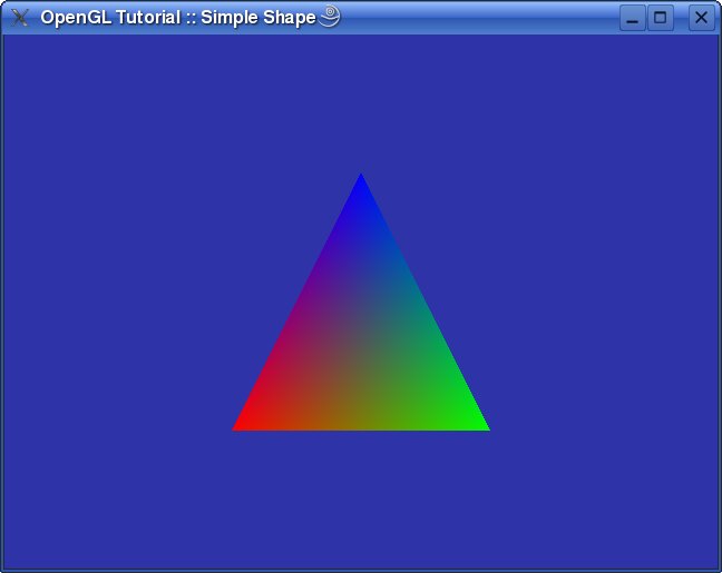
OK... and now, the code for drawing the first shape:
procedure DrawGLScene; cdecl;
begin
  glClear(GL_COLOR_BUFFER_BIT or GL_DEPTH_BUFFER_BIT);

  glLoadIdentity;
  glTranslatef(0, 0, -5);

  glBegin(GL_TRIANGLES);
    glColor3f(1, 0, 0);
    glVertex3f(-1, -1, 0);

    glColor3f(0, 1, 0);
    glVertex3f(1, -1, 0);

    glColor3f(0, 0, 1);
    glVertex3f(0, 1, 0);
  glEnd;

  glutSwapBuffers;
end;
We have allready used glClear function. It will just reset buffers. We'll skip next two functions and head for drawing ones.
glBegin marks beginning of drawing block. After this function you can start entering vertices. Parameter describes how are vertices used when drawing: GL_POINTS: Treats each vertex as a single point. Vertex n defines point n. N points are drawn.
GL_LINES: Treats each pair of vertices as an independent line segment. Vertices 2n-1 and 2n define line n. n/2 lines are drawn.
GL_LINE_STRIP: Draws a connected group of line segments from the first vertex to the last. n-1 lines are drawn.
GL_LINE_LOOP: Draws a connected group of line segments from the first vertex to the last, then back to the first. Vertices n and n+1 define line n. The last line, however, is defined by vertices n and 1. n lines are drawn.
GL_TRIANGLES: Treats each triplet of vertices as an independent triangle. Vertices 3n-2, 3n-1 and 3n define triangle n. n/3 triangles are drawn.
GL_TRIANGLE_STRIP: Draws a connected group of triangles. One triangle is defined for each vertex presented after the first two vertices. For odd n, vertices n, n+1 and n+2 define triangle n. For even n, vertices n+1, n and n+2 define triangle n. n-2 triangles are drawn.
GL_TRIANGLE_FAN: Draws a connected group of triangles. One triangle is defined for each vertex presented after the first two vertices. Vertices 1. n+1 and n+2 define triangle n. n-2 triangles are drawn.
GL_QUADS: Treats each group of four vertices as an independent quadrilateral. Vertices 4n-3, 4n-2, 4n-1 and 4n define quadrilateral n. n/4 quadrilaterals are drawn.
GL_QUAD_STRIP: Draws a connected group of quadrilaterals. One quadrilateral is defined for each pair of vertices presented after the first pair. Vertices 2n-1, 2n, 2n+2 and 2n+1 define quadrilateral n. n/2-1 quadrilaterals are drawn. Note that the order in which vertices are used to construct a quadrilateral from strip data is different from that used with independent data.
GL_POLYGON: Draws a single, convex polygon. Vertices 1 through n define this polygon.
You'll draw single triangle and for that GL_TRIANGLES flag will do the trick. glVertex3f function defines the position of a vertex you want to draw. There are more glVertex* functions. Only difference is number and type of parameters they take. For instance... glVertex2i takes two parameters (x and y) of integer type. glVertex3f will almost always be just what you need.
Before glVertex you can set color, material, texture... For simplicity you'll just specify color for each vertex in this tutorial. Color is set using glColor3f function. glColor can also take different set of parameters like glVertex.
As we look through code we can see that Z is set to 0 for all vertices. Since you set near plane to 0.1, triangle will not be visible. That is where those two functions we skipped in the beginning jump in. We already know that glLoadIdentity reset matrix. glTranslatef moves triangles by X, Y and Z values you provide. Since you set Z to -5 (negative Z is farther from camera) all vertices will be drawn 5 units far from point of view and will be visible.
In the end you call glEnd functions that finishes drawing. You could now start another drawing block with new glBegin function if you wish.
Download source code, linux executable or windows executable from Lazarus CCR SourceForge.
Using display lists
Sometimes you'll need to draw some object multiple times on scene. OpenGL has ability to build display lists which make drawing a bit faster. Creating display list is very easy... just draw vertices as you did in previous tutorial and enclose them with glNewList and glEndList calls.
const
  LIST_OBJECT = 1;

procedure CreateList;
begin
  glNewList(LIST_OBJECT, GL_COMPILE);
    glBegin(GL_TRIANGLE_FAN);
      glColor3f(1, 0, 0);
      glVertex3f(0, 0.5, 0);

      glColor3f(1, 1, 0);
      glVertex3f(-0.5, -0.5, 0.5);

      glColor3f(1, 1, 1);
      glVertex3f(0.5, -0.5, 0.5);

      glColor3f(0, 1, 1);
      glVertex3f(0.5, -0.5, -0.5);

      glColor3f(0, 0, 1);
      glVertex3f(-0.5, -0.5, -0.5);

      glColor3f(0, 1, 0);
      glVertex3f(-0.5, -0.5, 0.5);
    glEnd;

    glBegin(GL_QUADS);
      glColor3f(1, 1, 0);
      glVertex3f(-0.5, -0.5, 0.5);

      glColor3f(1, 1, 1);
      glVertex3f(0.5, -0.5, 0.5);

      glColor3f(0, 1, 1);
      glVertex3f(0.5, -0.5, -0.5);

      glColor3f(0, 0, 1);
      glVertex3f(-0.5, -0.5, -0.5);

      glColor3f(0, 1, 0);
      glVertex3f(-0.5, -0.5, 0.5);
    glEnd;
  glEndList;
end;
glNewList creates new display list and all drawing functions will be recorded until glEndList is called. The first parameter for glNewList function is list ID. Every list is defined by it's ID. If list with given ID is already created it fill be cleared before recording. If the second parameter is GL_COMPILE then all drawing functions are just recorded, but if it is GL_COMPILE_AND_EXECUTE then they are recorded and executed automaticly.
glIsList function can help you with display lists. It can tell if some list ID is already filled with data. Another useful function is glGenLists. It will create multiple empty display lists. You pass number of display lists you need and you get ID of the first one. If you require n lists, and get r ID, generated display lists are: r, r+1, r+2,..., r+n-1
All created lists should be deleted. You will do that before program exits:
procedure GLKeyboard(Key: Byte; X, Y: Longint); cdecl;
begin
  if Key = 27 then
  begin
    glDeleteLists(LIST_OBJECT, 1);
    Halt(0);
  end;
end;
glDeleteLists takes 2 parameters, ID of display list and number of lists to delete. If ID is r, and number of lists to delete is n, deleted lists are: r, r+1, r+2,..., r+n-1
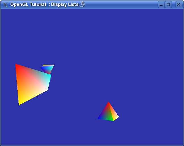
Now you know how to create and delete display lists... let's see how to draw them:
procedure DrawGLScene; cdecl;
begin
  glClear(GL_COLOR_BUFFER_BIT or GL_DEPTH_BUFFER_BIT);

  glLoadIdentity;
  glTranslatef(-2, 0, -5);
  glRotatef(40, 1, 0, 1);
  glCallList(LIST_OBJECT);

  glLoadIdentity;
  glTranslatef(1, -2, -10);
  glRotatef(62, 0, 1, 0);
  glCallList(LIST_OBJECT);

  glLoadIdentity;
  glTranslatef(-4, 0.5, -15);
  glRotatef(200, 1, 0, 0);
  glCallList(LIST_OBJECT);

  glutSwapBuffers;
end;
Using glCallList you can draw only one display list. In this tutorial, before drawing display list, you change model matrix and draw object in different places.
Some times you would like to draw multiple lists at once. That is possible using glCallLists function. It takes number of lists you want to draw, type of array that contains display list IDs and array with display list IDs. Type of list can be one of the following:
GL_BYTE: list is treated as an array of signed bytes, each in the range -128 through 127.
GL_UNSIGNED_BYTE: list is treated as an array of unsigned bytes, each in the range 0 through 255.
GL_SHORT: list is treated as an array of signed two-byte integers, each in the range -32768 through 32767.
GL_UNSIGNED_SHORT: list is treated as an array of unsigned two-byte integers, each in the range 0 through 65535.
GL_INT: lists is treated as an array of signed four-byte integers.
GL_UNSIGNED_INT: list is treated as an array of unsigned four-byte integers.
GL_FLOAT: list is treated as an array of four-byte floating-point values.
GL_2_BYTES: list is treated as an array of unsigned bytes. Each pair of bytes specifies a single display list ID. The value of the pair is computed as 256 times the unsigned value of the first byte plus the unsigned value of the second byte.
GL_3_BYTES: list is treated as an array of unsigned bytes. Each triplet of bytes specifies a single display list ID. The value of the triplet is computed as 65536 times the unsigned value of the first byte, plus 256 times the unsigned value of the second byte, plus the unsigned value of the third byte.
GL_4_BYTES: list is treated as an array of unsigned bytes. Each quadruplet of bytes specifies a single display list ID. The value of the quadruplet is computed as 16777216 times the unsigned value of the first byte, plus 65536 times the unsigned value of the second byte, plus 256 times the unsigned value of the third byte, plus the unsigned value of the fourth byte.
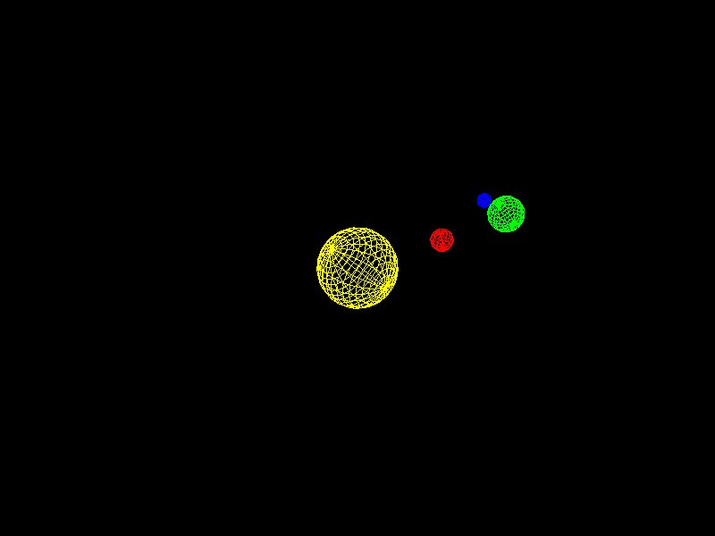
That is for now. Next tutorial will show how to create little planetary system. We'll talk about matrices and how to make animated scene that doesn't depend of number of frames per second.
Download source code, linux executable or windows executable from Lazarus CCR SourceForge.
Full screen animation
Entering full screen mode is easy with GLUT. Let's change main part of the program:
const
  FSMode = '800x600:32@75';

begin
  glutInitPascal(False);
  glutInitDisplayMode(GLUT_DOUBLE or GLUT_RGB or GLUT_DEPTH);
  glutGameModeString(FSMode);
  glutEnterGameMode;
  glutSetCursor(GLUT_CURSOR_NONE);

  InitializeGL;

  glutDisplayFunc(@DrawGLScene);
  glutReshapeFunc(@ReSizeGLScene);
  glutKeyboardFunc(@GLKeyboard);
  glutIdleFunc(@DrawGLScene);

  glutMainLoop;
end.
Since we don't want GLUT to parse command line this time we call glutInitPascal with False parameter. As you can see, there is no code for window creation. GLUT have glutEnterGameMode that create full screen window. To specify what kind of full screen mode you want, you call glutGameModeString function which takes string that defines mode you like. Format of that string is:
[width "x" height][":" bpp]["@" hertz]
In FSMode string we declared that full screen mode should be 800x600, with 32bit pallete and 75Hz refresh. It is possible to skip one of the group. If you omit size, GLUT will try to use current one or first smaller that can work. That policy is used and for other parameters.
Usually in full screen mode cursor is not visible. To hide cursor you use glutSetCursor function. It takes only one parameter which describes cursor you would like to see:
GLUT_CURSOR_RIGHT_ARROW
GLUT_CURSOR_LEFT_ARROW
GLUT_CURSOR_INFO
GLUT_CURSOR_DESTROY
GLUT_CURSOR_HELP
GLUT_CURSOR_CYCLE
GLUT_CURSOR_SPRAY
GLUT_CURSOR_WAIT
GLUT_CURSOR_TEXT
GLUT_CURSOR_CROSSHAIR
GLUT_CURSOR_UP_DOWN
GLUT_CURSOR_LEFT_RIGHT
GLUT_CURSOR_TOP_SIDE
GLUT_CURSOR_BOTTOM_SIDE
GLUT_CURSOR_LEFT_SIDE
GLUT_CURSOR_RIGHT_SIDE
GLUT_CURSOR_TOP_LEFT_CORNER
GLUT_CURSOR_TOP_RIGHT_CORNER
GLUT_CURSOR_BOTTOM_RIGHT_CORNER
GLUT_CURSOR_BOTTOM_LEFT_CORNER
GLUT_CURSOR_FULL_CROSSHAIR
GLUT_CURSOR_NONE
GLUT_CURSOR_INHERIT
glutIdleFunc defines callback function that you want to be called every time you program has no messages to process. Since we just want to render new frame if there is nothing to do, just set idle function to DrawGLScene. Some other tutorials show that idle function should send refresh message insted of drawing, but that way I have 50-100 frames less than using method I described.
Now, let's look at the program termination where you need to exit full screen mode:
procedure GLKeyboard(Key: Byte; X, Y: Longint); cdecl;
begin
  if Key = 27 then
  begin
    glutLeaveGameMode;
    Halt(0);
  end;
end;
As you can see, all you need to do is to call glutLeaveGameMode.
Now, we'll introduce some new matrix functions. First, let's change ReSizeGLScene function:
procedure ReSizeGLScene(Width, Height: Integer); cdecl;
begin
  .
  .
  .
  glMatrixMode(GL_MODELVIEW);
  glLoadIdentity;
  gluLookAt(0, 20, 25, 0, 0, 0, 0, 1, 0);
end;
gluLookAt create matrix that will define from where are you look to objects. First 3 parameters are X, Y and Z coordinate of position of camera. Next 3 parameters are X, Y and Z coordinate of point where camera look at, and last 3 parameters defines "up" vector (where is "up" for the camera). Usually, up is positive y axis.
OK, let's draw now. Since you set matrix with gluLookAt that should be used with all objects, you can't just use glLoadIdentity to reset matrix for next object... you'll save previous matrix state and restore it after object is drawn:
procedure DrawGLScene; cdecl;
var
  T: Single;
begin
  T := glutGet(GLUT_ELAPSED_TIME) / 1000;
  glClear(GL_COLOR_BUFFER_BIT or GL_DEPTH_BUFFER_BIT);

  glPushMatrix;
    glRotatef(5 * T, 0, 1, 0);
    glColor3f(1, 1, 0);
    glutWireSphere(2, 20, 20);
  glPopMatrix;

  glPushMatrix;
    glRotatef(90 * T, 0, 1, 0);
    glTranslatef(5, 0, 0);
    glRotatef(40 * T, 0, 1, 0);
    glColor3f(1, 0, 0);
    glutWireSphere(0.6, 10, 10);
  glPopMatrix;

  glPushMatrix;
    glRotatef(60 * T, 0, 1, 0);
    glTranslatef(-3, 0, 9);
    glRotatef(50 * T, 0, 1, 0);
    glColor3f(0, 1, 0);
    glutWireSphere(1, 16, 16);

    glPushMatrix;
      glRotatef(360 * T, 0, 1, 0);
      glTranslatef(-1.7, 0, 0);
      glRotatef(50 * T, 0, 1, 0);
      glColor3f(0, 0, 1);
      glutWireSphere(0.4, 10, 10);
    glPopMatrix;

  glPopMatrix;

  glutSwapBuffers;
end;
glPushMatrix i glPopMatrix are used to save and restore matrix state. As you can see, we save matrix state, then change matrix in order to draw object in right place, and then restore old matrix state.
You may wonder what is T variable for. Well, it is used to determen animation speed. Every change that depends on time is multiplied with T. That way animation speed is constant on every frame rate. glutGet function with GLUT_ELAPSED_TIME parameter returns time in milliseconds from glutInit is called. By dividing that value with 1000, we get time in seconds.
glRotatef function create rotation matrix. First parameter is angle in degrees, and last 3 parameters defines axis around which rotation will be done. Since you multiplied angle with T, object will be rotated by that angle in exactly 1 second.
Download source code, linux executable or windows executable from Lazarus CCR SourceForge.
Light
This tutorial will introduce some light to the scene. You'll make rotating cube and one light which will add some realism to the scene, but first let's make some utility unit.
For now it will have only basic functions to help us getting current and delta (time that elapsed from one render to other render call) times and for calculating frames per second.
unit utils;

{$mode objfpc}{$H+}

interface

uses
  glut;

function GetTotalTime: Single;
function GetDeltaTime: Single;
procedure FrameRendered(Count: Integer = 1);
function GetFPS: Single;

implementation

var
  OldTime: Integer = 0;
  FPSTime: Integer = 0;
  FPSCount: Integer = 0;

function GetTotalTime: Single;
begin
  Result := glutGet(GLUT_ELAPSED_TIME) / 1000;
end;

function GetDeltaTime: Single;
var
  NewTime: Integer;
begin
  NewTime := glutGet(GLUT_ELAPSED_TIME);
  Result := (NewTime - OldTime) / 1000;
  OldTime := NewTime;
end;

procedure FrameRendered(Count: Integer);
begin
  Inc(FPSCount, Count);
end;

function GetFPS: Single;
var
  NewTime: Integer;
begin
  NewTime := glutGet(GLUT_ELAPSED_TIME);

  Result := FPSCount / ((NewTime - FPSTime) / 1000);

  FPSTime := NewTime;
  FPSCount := 0;
end;

end.
As you can see, there is nothing complicated in this unit. Time is simply saved betwen calls and difference is returned. FrameRendered should be called every time you draw scene so function can calculate FPS.
Now, let's have fun with lights.
OpenGL have several types of light... ambient, diffuse, point, spot, specular and emissive light.
Ambient light is something like Sun. When sun rays pass through the window of a room they hit the walls and are reflected and scattered into all different directions which averagely brightens up the whole room. All vertices are lit with ambient light.
Diffuse light can be represented as parallel light rays comming from far away. They will lit only vertices that are oriented towards the light source.
Point light lights all around it. It is like a fire ball, it send light rays all around it and lights vertices that are oriented towards light source and that are close enough.
Spot light is like light from flashlight. It is simply a point light source with a small light cone radius. All vertices that falls inside of cone and are close enough are lit.
Just like Diffuse light, Specular light is a directional type of light. It comes from one particular direction. The difference between the two is that specular light reflects off the surface in a sharp and uniform way. The rendering of specular light relies on the angle between the viewer and the light source. From the viewer’s standpoint specular light creates a highlighted area on the surface of the viewed object known as specular highlight or specular reflection.
Emissive light is a little different than any other previously explained light components. This light comes out of object you draw but don't lit other objects in nearby.
For simplicity we'll use only diffuse light in this tutorial. Later on, some other lights may appear in tutorials :)
Let's see how to enable light in scene:
const
  DiffuseLight: array[0..3] of GLfloat = (0.8, 0.8, 0.8, 1);

  glEnable(GL_LIGHTING);
  glLightfv(GL_LIGHT0, GL_DIFFUSE, DiffuseLight);
  glEnable(GL_LIGHT0);
As you see, we enable lighting in OpenGL so lights affect scene you are rendering. Light parameters are set with glLightfv function. It takes 3 parameters... one for light number you want to change (OpenGL suports up to 8 lights), next tells OpenGL what light parameter to change, and the last one is new parameter for light. You'll set just diffuse color for light in this tutorial. After that, you can enable light and there will be light in the scene... but... that is not all.
More about glLightfv: http://www.opengl.org//documentation/specs/man_pages/hardcopy/GL/html/gl/light.html
If you want to use lights you can't just set color for vertex... you must set material for vertices. Let's setup material for drawing:
glEnable(GL_COLOR_MATERIAL);
glColorMaterial(GL_FRONT, GL_AMBIENT_AND_DIFFUSE);
You expected something more complicated, do you? :) Well, this code allows us to use glColor function to set material to vertices. By using glEnable function and GL_COLOR_MATERIAL flag, you can define what material properties will glColor change. glColorMaterial(GL_FRONT, GL_AMBIENT_AND_DIFFUSE) tells OpenGL that glColor changes ambient and diffuse material. We'll discus materials more in later tutorials.
One more thing that is important when using lights... every vertex must have normal associated with it. Normal is used to find the direction of vertex so light can be calculated properly. You'll use GLUT function to draw cube and it provides normals for us, so this time we'll just walk by normals.
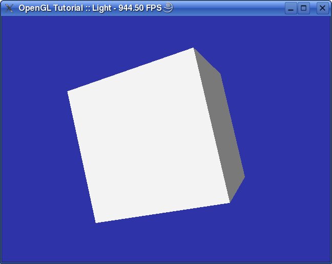
After all those setting ups, light will shine up your cube :)
Part of the text is copied from The OpenGL Light Bible
Download source code, linux executable or windows executable from Lazarus CCR SourceForge.
Bitmap fonts
Games and programs usually need to write some text on screen. GLUT provides several functions for drawing chars that are platform independent.
First, we'll show how to use default bitmap fonts. Almost all code additions will be made to utils.pas unit.
Since text will be drawn in 2D, we'll need to know width and height of viewport... so, we'll write two functions for that:
function glGetViewportWidth: Integer;
var
  Rect: array[0..3] of Integer;
begin
  glGetIntegerv(GL_VIEWPORT, @Rect);
  Result := Rect[2] - Rect[0];
end;

function glGetViewportHeight: Integer;
var
  Rect: array[0..3] of Integer;
begin
  glGetIntegerv(GL_VIEWPORT, @Rect);
  Result := Rect[3] - Rect[1];
end;
We just get left/right, top/bottom and calculate width/height by subtracting them.
There must be functions for entering and leaving 2D mode:
procedure glEnter2D;
begin
  glMatrixMode(GL_PROJECTION);
  glPushMatrix;
  glLoadIdentity;
  gluOrtho2D(0, glGetViewportWidth, 0, glGetViewportHeight);

  glMatrixMode(GL_MODELVIEW);
  glPushMatrix;
  glLoadIdentity;

  glDisable(GL_DEPTH_TEST);
end;

procedure glLeave2D;
begin
  glMatrixMode(GL_PROJECTION);
  glPopMatrix;
  glMatrixMode(GL_MODELVIEW);
  glPopMatrix;

  glEnable(GL_DEPTH_TEST);
end;
When entering 2D mode, we save current matrices and set 2D matrix using gluOrtho2D function. This way if we draw some thing on 100, 100 it will be drawn on exactly 100 pixels from left edge of window, and 100 pixels form bottom edge (positive Y is up). Also, we disable ZBuffer. This way text won't alter ZBuffer.
Leaving 2D mode just returns old matrices and enable ZBuffer.
Now, we can create function for text drawing:
procedure glWrite(X, Y: GLfloat; Font: Pointer; Text: String);
var
  I: Integer;
begin
  glRasterPos2f(X, Y);
  for I := 1 to Length(Text) do
    glutBitmapCharacter(Font, Integer(Text[I]));
end;
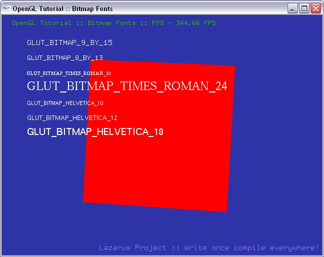
glutBitmapCharacter can draw only one character of selected font. First parameter is desired font (GLUT_BITMAP_9_BY_15, GLUT_BITMAP_8_BY_13, GLUT_BITMAP_TIMES_ROMAN_10, GLUT_BITMAP_TIMES_ROMAN_24, GLUT_BITMAP_HELVETICA_10, GLUT_BITMAP_HELVETICA_12 or GLUT_BITMAP_HELVETICA_18) and other one is character.
Character will be drawn at current raster position. To set desired raster position we call glRasterPos function. glRasterPos can handle different number and types of parameters just like glVertex function. Coordinate specified is transformed by model and projection matrix to get 2D coordinate where new raster position will be. Since we entered 2D mode, X and Y coordinates are actual 2D coordinates where drawing will occur.
This new functions will make text drawing very easy:
procedure DrawGLScene; cdecl;
begin
  glClear(GL_COLOR_BUFFER_BIT or GL_DEPTH_BUFFER_BIT);

  glLoadIdentity;
  glTranslatef(0, 0, -5);
  glRotatef(GetTotalTime * 10, 0, 0.5, 0.5);

  glColor3f(1, 0, 0);
  glutSolidCube(2);

  glEnter2D;

  glColor3f(0.2, 0.8 + 0.2 * Sin(GetTotalTime * 5), 0);
  glWrite(20, glGetViewportHeight - 20, GLUT_BITMAP_8_BY_13,
    Format('OpenGL Tutorial :: Bitmap Fonts :: FPS - %.2f FPS', [FPS]));

  glColor3f(1, 1, 1);
  glWrite(50, glGetViewportHeight - 60, GLUT_BITMAP_9_BY_15, 'GLUT_BITMAP_9_BY_15');
  glWrite(50, glGetViewportHeight - 90, GLUT_BITMAP_8_BY_13, 'GLUT_BITMAP_8_BY_13');
  glWrite(50, glGetViewportHeight - 120, GLUT_BITMAP_TIMES_ROMAN_10, 'GLUT_BITMAP_TIMES_ROMAN_10');
  glWrite(50, glGetViewportHeight - 150, GLUT_BITMAP_TIMES_ROMAN_24, 'GLUT_BITMAP_TIMES_ROMAN_24');
  glWrite(50, glGetViewportHeight - 180, GLUT_BITMAP_HELVETICA_10, 'GLUT_BITMAP_HELVETICA_10');
  glWrite(50, glGetViewportHeight - 210, GLUT_BITMAP_HELVETICA_12, 'GLUT_BITMAP_HELVETICA_12');
  glWrite(50, glGetViewportHeight - 240, GLUT_BITMAP_HELVETICA_18, 'GLUT_BITMAP_HELVETICA_18');

  glColor3f(0.5, 0.5, 1);
  glWrite(
    glGetViewportWidth - glutBitmapLength(GLUT_BITMAP_9_BY_15, LazText) - 5,
    10, GLUT_BITMAP_9_BY_15, LazText);

  glLeave2D;

  glutSwapBuffers;

  FrameRendered;
end;
We draw red cube and rotate it, and some text to show how various bitmap fonts look like. glutBitmapLength function is used to find width of string so it could be aligned to right. Code can easily be altered to center text.
Note: See how cube looks without light.
Download source code, linux executable or windows executable from Lazarus CCR SourceForge.
Textures
It's time to use textures :)
This tutorial will show how to draw textured polygons and how to blend textures using multipass technic. Since OpenGL has no builtin mechanism for loading textures, we'll use external library: Vampyre Imaging Library. We'll use just OpenGL helper functions, but you may find this lib handy for some other things to.
Let's get started... we'll create display list for drawing textured rectangle:
procedure CreateList;
begin
  glNewList(LIST_OBJECT, GL_COMPILE);
    glBegin(GL_QUADS);
      glTexCoord2f(1, 0);
      glVertex3f( 2, 2, 0);
      glTexCoord2f(0, 0);
      glVertex3f(-2, 2, 0);
      glTexCoord2f(0, 1);
      glVertex3f(-2,-2, 0);
      glTexCoord2f(1, 1);
      glVertex3f( 2,-2, 0);
    glEnd;
  glEndList;
end;
Notice glTexCoord functions. They are used to specify which part of texture is assigned to vertex. Coordinates defined in this functions are from 0 to 1 (values greater than 1 are allowed but can generate different results). 0 is first pixel and 1 is last pixel. So, 0.5 will be right in the middle of texture.
Texture loading is extremely easy with Vampyre Imaging Library:
var
  Tex1, Tex2: GLuint;

procedure InitializeGL;
begin
  glClearColor(0, 0, 0, 0);
  Tex1 := LoadGLTextureFromFile('ashwood.bmp');
  Tex2 := LoadGLTextureFromFile('Flare.bmp');
  glEnable(GL_TEXTURE_2D);
end;
LoadGLTextureFromFile loads texture from file and returns it's ID. When texture is loaded it is allready setup for rendering. Last line just enables 2D textures.
To draw textured polygon you have to bind texture and setup texture coordinations (texture coordinations are set in display list in this tutorial):
  ...
  glLoadIdentity;
  glTranslatef(-5, 0, -15);
  glBindTexture(GL_TEXTURE_2D, Tex1);
  glCallList(LIST_OBJECT);
  ...
glBindTexture function is used to select texture. When you draw polygins they will have selected texture on them. It's that easy :)
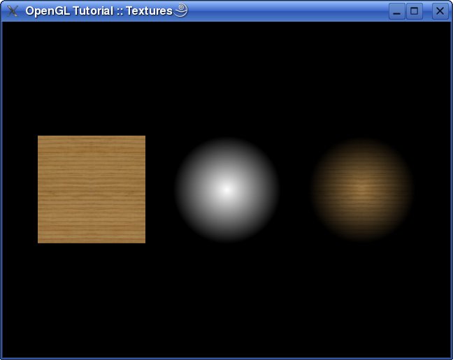
So, using one texture is easy... but how to blend two textures. Basicly you draw polygon once with one texture, setup blending parameters, and draw polygon once more time with other texture. You can blend houndreds of textures this way. Let's see how code for this looks:
  ...
  glLoadIdentity;
  glTranslatef(5, 0, -15);
  glBindTexture(GL_TEXTURE_2D, Tex1);
  glCallList(LIST_OBJECT);

  glEnable(GL_BLEND);
  glBlendFunc(GL_ZERO, GL_SRC_COLOR);
  glLoadIdentity;
  glTranslatef(5, 0, -15);
  glBindTexture(GL_TEXTURE_2D, Tex2);
  glCallList(LIST_OBJECT);
  glDisable(GL_BLEND);
...
As you can see, polygon is drawn first time like we allready know. Before second drawing we enable blending by calling glEnable(GL_BLEND). Blending means that finall pixel color is calculated like this:
DrawingColor * SRCBLEND + BackgroundColor * DESTBLEND
SRCBLEND and DESTBLEND are defined using glBlendFunc function. In this tutorial we set SRCBLEND to GL_ZERO (zero) and DESTBLENT to GL_SRC_COLOR (DrawingColor) and finall color is then:
DrawingColor * 0 + BackgroundColor * DrawingColor
This means that background will get darker when you draw with dark colors... when you draw with white color, background color will not be changed. The result will look like this
Next time, we'll use extensions to show how to use singlepass multitexturing.
Download source code, linux executable or windows executable from Lazarus CCR SourceForge.
Multitexturing (extensions)
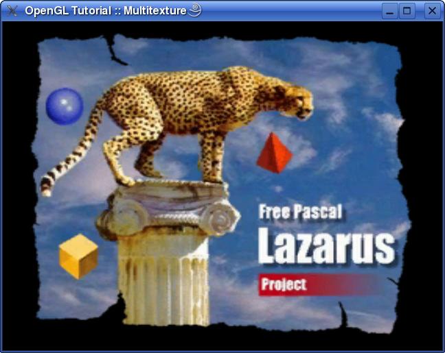
When youknow multipass multi texturing, singlepass is very easy. Texturing is separated in stages. First stage setup and draw first texture, second stage draws another one and so on. All you have to do is to setup texture stages and to render object.
Let's see how code looks like:
procedure InitializeGL;
begin
  Load_GL_ARB_multitexture;
  glClearColor(0, 0, 0, 0);
  Tex1 := LoadGLTextureFromFile('Lazarus.bmp');
  Tex2 := LoadGLTextureFromFile('Mask.bmp');
  glActiveTextureARB(GL_TEXTURE0_ARB);
  glEnable(GL_TEXTURE_2D);
  glBindTexture(GL_TEXTURE_2D, Tex1);
  glActiveTextureARB(GL_TEXTURE1_ARB);
  glEnable(GL_TEXTURE_2D);
  glBindTexture(GL_TEXTURE_2D, Tex2);
end;
First we need load OpenGL extension that will allow us to use multitexture functions. Load_GL_ARB_multitexture will try to load those extensions and will return TRUE if operation was successful.
To select texture stage you want to work on, use glActiveTextureARB function. It takes only one parameter that define which stage you want. After that all texture functions (enabling, disabling, binding, creating...) will affect that stage.
Since we setup every thing in initialization function, all we have to do is to draw object:
procedure DrawGLScene; cdecl;
begin
  glClear(GL_COLOR_BUFFER_BIT or GL_DEPTH_BUFFER_BIT);

  glLoadIdentity;
  glTranslatef(0, 0, -5);

  glBegin(GL_QUADS);
    glMultiTexCoord2fARB(GL_TEXTURE0_ARB, 1, 0);
    glMultiTexCoord2fARB(GL_TEXTURE1_ARB, 1, 0);
    glVertex3f(2.516, 2, 0);
    glMultiTexCoord2fARB(GL_TEXTURE0_ARB, 0, 0);
    glMultiTexCoord2fARB(GL_TEXTURE1_ARB, 0, 0);
    glVertex3f(-2.516, 2, 0);
    glMultiTexCoord2fARB(GL_TEXTURE0_ARB, 0, 1);
    glMultiTexCoord2fARB(GL_TEXTURE1_ARB, 0, 1);
    glVertex3f(-2.516,-2, 0);
    glMultiTexCoord2fARB(GL_TEXTURE0_ARB, 1, 1);
    glMultiTexCoord2fARB(GL_TEXTURE1_ARB, 1, 1);
    glVertex3f(2.516,-2, 0);
  glEnd;

  glutSwapBuffers;
end;
As you can see, difference is only in defining texture coordinations. We now use glMultiTexCoord2fARB function that takes texture stage and texture coordinations. Every thing else is unchanged.
Today almost all graphic cards supports at least 2 texture stages. Using singlepass multitexturing is faster than multipass version since you draw objects only once. If hardware supports singlepass multitexturing (Load_GL_ARB_multitexture returns TRUE) use it.
Download source code, linux executable or windows executable from Lazarus CCR SourceForge.
Render to texture
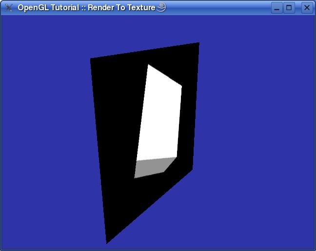
This one will be short. OpenGL can capture current scene to texture so you can use it for texturing other objects (TV screen, mirror or some thing else). Well just render scene to texture and apply it to rotating plane.
First, we must create empty texture which we'll use to capture scene:
procedure SetupRenderTexture;
var
  Data: Pointer;
begin
  GetMem(Data, 256*256*3);
  glGenTextures(1, @RenderTexture);
  glBindTexture(GL_TEXTURE_2D, RenderTexture);
  glTexImage2D(GL_TEXTURE_2D, 0, 3, 256, 256, 0, GL_RGB, GL_UNSIGNED_BYTE, Data);
  glTexParameteri(GL_TEXTURE_2D, GL_TEXTURE_MAG_FILTER, GL_LINEAR);
  glTexParameteri(GL_TEXTURE_2D, GL_TEXTURE_MIN_FILTER, GL_LINEAR);
  FreeMem(Data);
end;
Buffer for 256*256 RGB image is created and it is used to setup 2D texture.
Main part is in drawing function:
procedure DrawGLScene; cdecl;
var
  TotalTime: Single;
begin
  glClearColor(0, 0, 0, 0);
  glClear(GL_COLOR_BUFFER_BIT or GL_DEPTH_BUFFER_BIT);
  glEnable(GL_LIGHTING);
  glDisable(GL_TEXTURE_2D);
  glViewport(0, 0, 256, 256);

  TotalTime := GetTotalTime;

  glLoadIdentity;
  glTranslatef(0, 0, -5);
  glRotatef(50 * TotalTime, 1, 0, 0);
  glRotatef(100 * TotalTime, 0, 1, 0);
  glRotatef(50 * TotalTime, 0, 0, 1);

  glColor3f(1, 1, 1);
  glutSolidCube(2);

  glCopyTexImage2D(GL_TEXTURE_2D, 0, GL_RGB, 0, 0, 256, 256, 0);

  glClearColor(0.18, 0.20, 0.66, 0);
  glClear(GL_COLOR_BUFFER_BIT or GL_DEPTH_BUFFER_BIT);
  glDisable(GL_LIGHTING);
  glEnable(GL_TEXTURE_2D);
  glViewport(0, 0, AppWidth, AppHeight);

  glLoadIdentity;
  glTranslatef(0, 0, -7);
  glRotatef(20 * TotalTime, 1, 0, 0);
  glRotatef(50 * TotalTime, 0, 1, 0);

  glBegin(GL_QUADS);
    glTexCoord2f(1, 0);
    glVertex3f(2, 2, 0);
    glTexCoord2f(0, 0);
    glVertex3f(-2, 2, 0);
    glTexCoord2f(0, 1);
    glVertex3f(-2,-2, 0);
    glTexCoord2f(1, 1);
    glVertex3f(2,-2, 0);
  glEnd;

  glutSwapBuffers;
end;
First, everything is setup for scene that will be captured. Viewport is reduced to 256*256 so it will fit into texture and scene is drawn. glCopyTexImage2D is used to capture scene to currently selected texture.
When we have scene captured to texture, everything can be cleared again, viewport can be returned to original size and final scene is drawn using previous scene as texture.
P.S. Captured texture can be saved using SaveGLTextureToFile function from Vampyre Imaging Library.
Download source code, linux executable or windows executable from Lazarus CCR SourceForge.
Vertex array
OpenGL is capable of rendering primitives using data that is stored in buffers insted of calling glVertex. Buffers can be used to define vertex and texture coordinates, and colors (index and RGBA), normals and edge flags.
In this tutorial well use only vertex and color buffers, and we'll show non-indexed and indexed drawing. Non-indexed mode draws buffers as streams. Indexed mode will draw buffer elements in order that is defined in index buffer. But enough talking... let's start coding.
First, let's define some types and constants:
type
  TVertex3f = record
    X, Y, Z: Single;
  end;

  TColor3f = record
   R, G, B: Single;
  end;

  VertexBuffer: array [0..5] of TVertex3f = (
    (X : 1; Y : 1; Z : 0),
    (X : -1; Y : 1; Z : 0),
    (X : -1; Y : -1; Z : 0),
    (X : 1; Y : 1; Z : 0),
    (X : -1; Y : -1; Z : 0),
    (X : 1; Y : -1; Z : 0)
  );
  ColorBuffer: array [0..5] of TColor3f = (
    (R : 1; G : 0; B : 1),
    (R : 0; G : 0; B : 1),
    (R : 0; G : 1; B : 0),
    (R : 1; G : 0; B : 1),
    (R : 0; G : 1; B : 0),
    (R : 1; G : 1; B : 0)
  );
We have two buffers. One for vertex coordinates and one for vertex colors. This 6 vertices defines 2 triangles that forms rectangle.
Drawing primitives using buffers is easy:
  glEnableClientState(GL_VERTEX_ARRAY);
  glEnableClientState(GL_COLOR_ARRAY);
  glVertexPointer(3, GL_FLOAT, 0, @VertexBuffer[0]);
  glColorPointer(3, GL_FLOAT, 0, @ColorBuffer[0]);

  glDrawArrays(GL_TRIANGLES, 0, Length(VertexBuffer));

  glDisableClientState(GL_VERTEX_ARRAY);
  glDisableClientState(GL_COLOR_ARRAY);
First we enable buffers we want to use using glEnableClientState function. Than we can select buffers we want to use. Every buffer type has own function for selecting (glColorPointer, glEdgeFlagPointer, glIndexPointer, glNormalPointer, glTexCoordPointer, glVertexPointer). First parameter in those functions defines how many numbers every element contains. For example, let's take vertex buffer. If this parameter is 2 than OpenGL expects that every element in buffer contains x and y coordinate. If this parameter is, for example, 4, than every element should contains x, y, z and w coordinate. Next parameter defines what type of data element contains (GL_BYTE, GL_UNSIGNED_BYTE, GL_SHORT, GL_UNSIGNED_SHORT, GL_INT, GL_UNSIGNED_INT, GL_FLOAT or GL_DOUBLE). Next one defines how many bytes are between each element. This way you can have buffer that contains vertex coordinates and some custom data. For arbitrary data type, this parameter can be calculated like this:
type
  TBufferData = record
    DataBefore: TDataBefore;
    Vertex: TVertex;
    DataAfter: TDataAfter;
  end;

Bytes between elements = SizeOf(TDataBefore) + SizeOf(TDataAfter)
Last parameter if pointer to the begginig of buffer.
When buffers are selected we can draw them using glDrawArrays functions. All enabled buffers are used to draw primitives. What kind of polygons are being generated is defined in first parameter (same as in glBegin function). Next two defines subset of buffer which is used for drawing (start and count).
When buffers are not needed you can disable them.
To demonstrate indexed mode, I made some simple mesh class that can load vertex, color and index data from external files:
type
  TMesh = class
  private
    FVertices: array of TVertex3f;
    FColors: array of TColor3f;
    FIndices: array of Integer;
    procedure FreeBuffers;
  public
    constructor Create;
    destructor Destroy; override;
    procedure LoadMesh(FileName: String);
    procedure DrawMesh;
  end;
FVertices will contain data about vertices, FColors data about color and FIndices data about indices when external file is loaded.
First we'll write some code that deals with creation and destruction of class:
procedure TMesh.FreeBuffers;
begin
  FVertices := nil;
  FColors := nil;
  FIndices := nil;
end;

constructor TMesh.Create;
begin
  FreeBuffers;
end;

destructor TMesh.Destroy;
begin
  FreeBuffers;
  inherited Destroy;
end;
File that will contain mesh data is simple text file. First row will contain number of vertices and indices separated by space character. After that row will come rows for every vertex and color. X, Y, Z, R, G and B all separated by space character. In the end, there will be rows for indices... every index number is written in its own row... so, for one triangle, data file will look like this:
3 3
-1 -1 0 1 1 1
1 -1 0 1 1 1
0 1 0 1 1 1
0
1
2
This means that there is 3 vertices and 3 indices defined in file. First vrtex is at -1, -1, 0 and has color 1, 1, 1 and so on. Indices defines that order in which vertices are drawn (in this case vertices are drawn in the same order as they are defined).
Code for loading this data will loke like this:
procedure TMesh.LoadMesh(FileName: String);
var
  MeshFile: TextFile;
  VertexCount, IndexCount: Integer;
  iV, iI: Integer;
begin
  FreeBuffers;

  AssignFile(MeshFile, FileName);
  Reset(MeshFile);

  ReadLn(MeshFile, VertexCount, IndexCount);

  SetLength(FVertices, VertexCount);
  SetLength(FColors, VertexCount);
  SetLength(FIndices, IndexCount);

  for iV := 0 to VertexCount - 1 do
    ReadLn(MeshFile,
      FVertices[iV].X, FVertices[iV].Y, FVertices[iV].Z,
      FColors[iV].R, FColors[iV].G, FColors[iV].B);

  for iI := 0 to IndexCount - 1 do
    ReadLn(MeshFile, FIndices[iI]);

  CloseFile(MeshFile);
end;
After loading data, we have everything for drawing:
procedure TMesh.DrawMesh;
begin
  glEnableClientState(GL_VERTEX_ARRAY);
  glEnableClientState(GL_COLOR_ARRAY);
  glVertexPointer(3, GL_FLOAT, 0, @FVertices[0]);
  glColorPointer(3, GL_FLOAT, 0, @FColors[0]);

  glDrawElements(GL_TRIANGLES, Length(FIndices), GL_UNSIGNED_INT, @FIndices[0]);

  glDisableClientState(GL_VERTEX_ARRAY);
  glDisableClientState(GL_COLOR_ARRAY);
end;
As you can see, allmost everything is the same as for non-indexed drawing, except function that actually draw polygons. In this case we use glDrawElements function. For this one we specify what kind of polygons we want, how many indices are in index buffer, type of data in index buffer and pointer to the beginning of index buffer.
Full source code comes with mesh data file that this class can use to generates rectangle that is identical with one that is drawn using non-indexed mode. Mesh data file looks like this:
4 6
1 1 0 1 0 1
-1 1 0 0 0 1
-1 -1 0 0 1 0
1 -1 0 1 1 0
0
1
2
0
2
3
As you can see, there is data for only 4 vertices and 6 indices. So, first triangle is defined by vertices 0, 1 and 2, and the seccond one by vertices 0, 2 and 3. By using indexed mode we don't have to duplicate vertices.
Download source code, linux executable or windows executable from Lazarus CCR SourceForge.
