Difference between revisions of "Lazarus on Raspberry Pi"
Jwdietrich (talk | contribs) |
|||
| Line 39: | Line 39: | ||
# Access through [[Lazarus on Raspberry Pi#2. Hardware access via encapsulated shell calls|encapsulated shell calls]] | # Access through [[Lazarus on Raspberry Pi#2. Hardware access via encapsulated shell calls|encapsulated shell calls]] | ||
# Access through the [[Lazarus on Raspberry Pi#3. wiringPi procedures and functions|wiringPi library]]. | # Access through the [[Lazarus on Raspberry Pi#3. wiringPi procedures and functions|wiringPi library]]. | ||
| + | # Access through Unit [[Lazarus_on_Raspberry_Pi/de#4._rpi_hal-Hardware Abstraction Library (GPIO, I2C and SPI Functions and Procedures)|rpi_hal]]. | ||
===1. Native hardware access=== | ===1. Native hardware access=== | ||
Revision as of 17:15, 25 May 2013
│
Deutsch (de) │
English (en) │
español (es) │
suomi (fi) │
中文(中国大陆) (zh_CN) │

The Raspberry Pi is a credit-card-sized single-board computer. It has been developed in the UK by the Raspberry Pi Foundation with the intention of stimulating the teaching of basic computer science in schools. Raspberry Pis are also used for multiple other purposes that are as different as media servers, robotics and control engineering.
The Raspberry Pi Foundation recommends Raspbian Wheezy as standard operating system. Alternative systems running on RPI include RISC OS and various Linux distributions, even Android.
Lazarus runs natively under the Raspbian operating system.
Installing and compiling Lazarus
Simple installation under Raspbian
In the Raspbian OS it is easy to install Lazarus and Free Pascal. In order to do this simply open a terminal window and type:
  sudo apt-get update
  sudo apt-get upgrade
  sudo apt-get install fpc
  sudo apt-get install lazarus
This installs a precompiled version of Lazarus on the Raspberry Pi. Of course, a network connection is required. Installation may take about 30 minutes, but major portions of this process take place automatically. After installation you may instantly start Lazarus from the "Programming" section of the LXDE start menu.
Compiling from sources
You may want to compile Lazarus from subversion sources. See Michell Computing: Lazarus on the Raspberry Pi for details.
Lazarus on Raspberry Pi
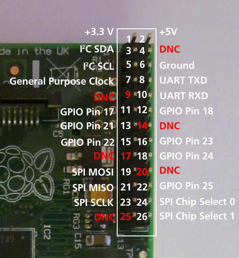
Numbering of GPIO pins


Accessing external hardware

One of the goals in the development of Raspberry Pi was to facilitate effortless access to external devices like sensors and actuators. There are three ways to access the IO facilities from Lazarus and Free Pascal:
- Direct access using the BaseUnix unit
- Access through encapsulated shell calls
- Access through the wiringPi library.
- Access through Unit rpi_hal.
1. Native hardware access


This method provides access to external hardware that doesn't require additional libraries. The only requirement is the BaseUnix library that is part of Free Pascal's RTL.
Switching a device via the GPIO port
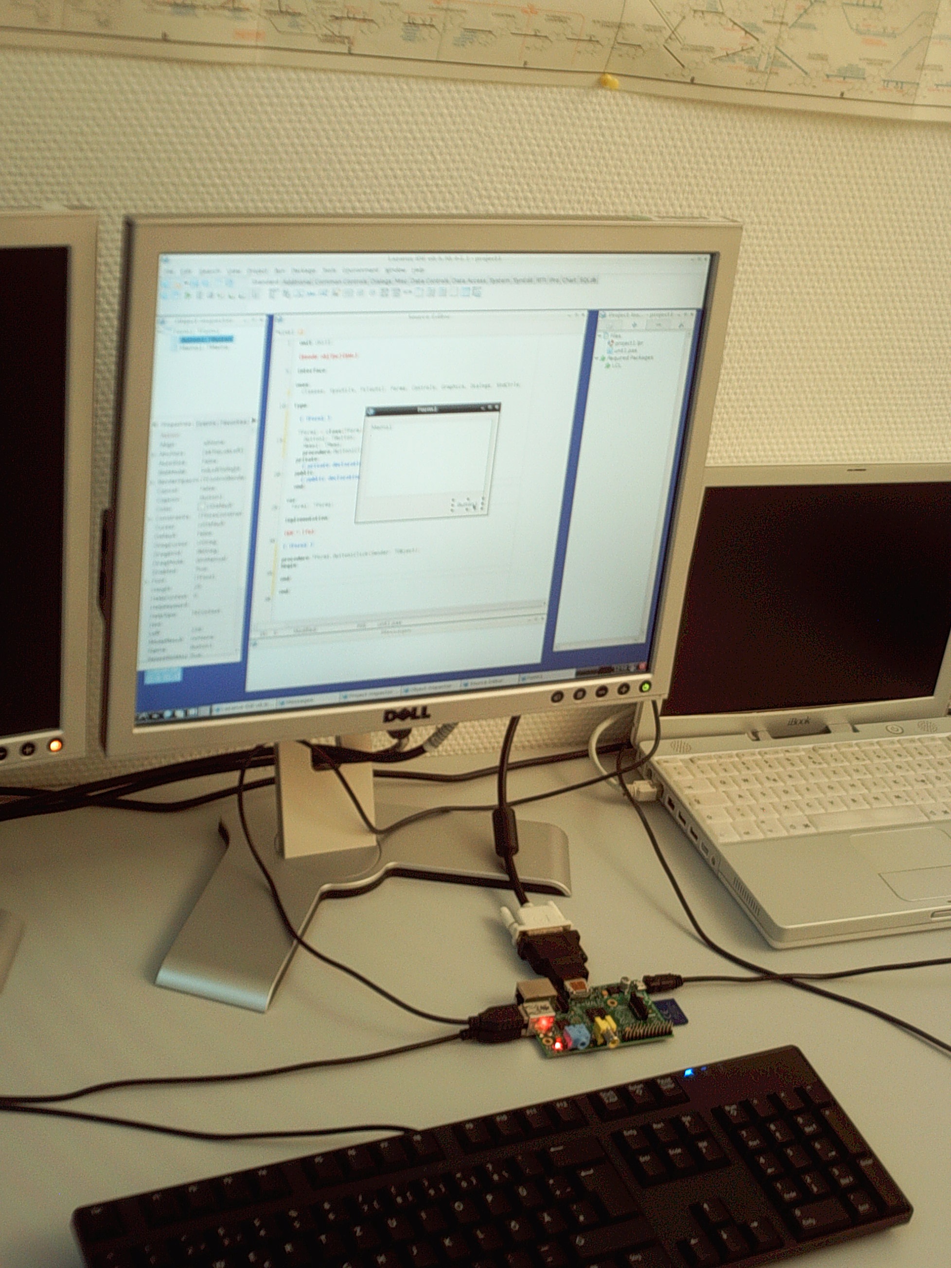
The following example lists a simple program that controls the GPIO pin 17 as output to switch an LED, transistor or relais. This program contains a ToggleBox with name GPIO17ToggleBox and for logging return codes a TMemo called LogMemo.
For the example, the anode of a LED has been connected with Pin 11 on the Pi's connector (corresponding to GPIO pin 17 of the BCM2835 SOC) and the LED's cathode was wired via a 68 Ohm resistor to pin 6 of the connector (GND) as previously described by Upton and Halfacree. Subsequently, the LED may be switched on and off with the application's toggle box.
The code requires to be run as root, i.e. either from a root account (not recommended) or via su.
Controlling unit:
unit Unit1;

{Demo application for GPIO on Raspberry Pi}
{Inspired by the Python input/output demo application by Gareth Halfacree}
{written for the Raspberry Pi User Guide, ISBN 978-1-118-46446-5}

{$mode objfpc}{$H+}

interface

uses
  Classes, SysUtils, FileUtil, Forms, Controls, Graphics, Dialogs, StdCtrls,
  Unix, BaseUnix;

type

  { TForm1 }

  TForm1 = class(TForm)
    LogMemo: TMemo;
    GPIO17ToggleBox: TToggleBox;
    procedure FormActivate(Sender: TObject);
    procedure FormClose(Sender: TObject; var CloseAction: TCloseAction);
    procedure GPIO17ToggleBoxChange(Sender: TObject);
  private
    { private declarations }
  public
    { public declarations }
  end;

const
  PIN_17: PChar = '17';
  PIN_ON: PChar = '1';
  PIN_OFF: PChar = '0';
  OUT_DIRECTION: PChar = 'out';

var
  Form1: TForm1;
  gReturnCode: longint; {stores the result of the IO operation}

implementation

{$R *.lfm}

{ TForm1 }

procedure TForm1.FormActivate(Sender: TObject);
var
  fileDesc: integer;
begin
  { Prepare SoC pin 17 (pin 11 on GPIO port) for access: }
  try
    fileDesc := fpopen('/sys/class/gpio/export', O_WrOnly);
    gReturnCode := fpwrite(fileDesc, PIN_17[0], 2);
    LogMemo.Lines.Add(IntToStr(gReturnCode));
  finally
    gReturnCode := fpclose(fileDesc);
    LogMemo.Lines.Add(IntToStr(gReturnCode));
  end;
  { Set SoC pin 17 as output: }
  try
    fileDesc := fpopen('/sys/class/gpio/gpio17/direction', O_WrOnly);
    gReturnCode := fpwrite(fileDesc, OUT_DIRECTION[0], 3);
    LogMemo.Lines.Add(IntToStr(gReturnCode));
  finally
    gReturnCode := fpclose(fileDesc);
    LogMemo.Lines.Add(IntToStr(gReturnCode));
  end;
end;

procedure TForm1.FormClose(Sender: TObject; var CloseAction: TCloseAction);
var
  fileDesc: integer;
begin
  { Free SoC pin 17: }
  try
    fileDesc := fpopen('/sys/class/gpio/unexport', O_WrOnly);
    gReturnCode := fpwrite(fileDesc, PIN_17[0], 2);
    LogMemo.Lines.Add(IntToStr(gReturnCode));
  finally
    gReturnCode := fpclose(fileDesc);
    LogMemo.Lines.Add(IntToStr(gReturnCode));
  end;
end;

procedure TForm1.GPIO17ToggleBoxChange(Sender: TObject);
var
  fileDesc: integer;
begin
  if GPIO17ToggleBox.Checked then
  begin
    { Swith SoC pin 17 on: }
    try
      fileDesc := fpopen('/sys/class/gpio/gpio17/value', O_WrOnly);
      gReturnCode := fpwrite(fileDesc, PIN_ON[0], 1);
      LogMemo.Lines.Add(IntToStr(gReturnCode));
    finally
      gReturnCode := fpclose(fileDesc);
      LogMemo.Lines.Add(IntToStr(gReturnCode));
    end;
  end
  else
  begin
    { Switch SoC pin 17 off: }
    try
      fileDesc := fpopen('/sys/class/gpio/gpio17/value', O_WrOnly);
      gReturnCode := fpwrite(fileDesc, PIN_OFF[0], 1);
      LogMemo.Lines.Add(IntToStr(gReturnCode));
    finally
      gReturnCode := fpclose(fileDesc);
      LogMemo.Lines.Add(IntToStr(gReturnCode));
    end;
  end;
end;

end.
Main program:
program io_test;

{$mode objfpc}{$H+}

uses
  {$IFDEF UNIX}{$IFDEF UseCThreads}
  cthreads,
  {$ENDIF}{$ENDIF}
  Interfaces, // this includes the LCL widgetset
  Forms, Unit1
  { you can add units after this };

{$R *.res}

begin
  Application.Initialize;
  Application.CreateForm(TForm1, Form1);
  Application.Run;
end.
Reading the status of a pin


Of course it is also possible to read the status of e.g. a switch that is connected to the GPIO port.
The following simple example is very similar to the previous one. It controls the GPIO pin 18 as input for a binary device like a switch, transistor or relais. This program contains a CheckBox with name GPIO18CheckBox and for logging return codes a TMemo called LogMemo.
For the example, one pole of a push-button has been connected to Pin 12 on the Pi's connector (corresponding to GPIO pin 18 of the BCM2835 SOC) and via a 10 kOhm pull-up resistor with pin 1 (+3.3V, see wiring diagram). The other pole has been wired to pin 6 of the connector (GND). The program senses the status of the button and correspondingly switches the CheckBox on or off, respectively.
Note that the potential of pin 18 is high if the button is released (by virtue of the connection to pin 1 via the pull-up resistor) and low if it is pressed (since in this situation pin 18 is connected to GND via the switch). Therefore, the GPIO pin signals 0 if the button is pressed and 1 if it is released.
This program has again to be executed as root.
Controlling unit:
unit Unit1;

{Demo application for GPIO on Raspberry Pi}
{Inspired by the Python input/output demo application by Gareth Halfacree}
{written for the Raspberry Pi User Guide, ISBN 978-1-118-46446-5}

{This application reads the status of a push-button}

{$mode objfpc}{$H+}

interface

uses
  Classes, SysUtils, FileUtil, Forms, Controls, Graphics, Dialogs, StdCtrls,
  ButtonPanel, Unix, BaseUnix;

type

  { TForm1 }

  TForm1 = class(TForm)
    ApplicationProperties1: TApplicationProperties;
    GPIO18CheckBox: TCheckBox;
    LogMemo: TMemo;
    procedure ApplicationProperties1Idle(Sender: TObject; var Done: Boolean);
    procedure FormActivate(Sender: TObject);
    procedure FormClose(Sender: TObject; var CloseAction: TCloseAction);
  private
    { private declarations }
  public
    { public declarations }
  end;

const
  PIN_18: PChar = '18';
  IN_DIRECTION: PChar = 'in';

var
  Form1: TForm1;
  gReturnCode: longint; {stores the result of the IO operation}

implementation

{$R *.lfm}

{ TForm1 }

procedure TForm1.FormActivate(Sender: TObject);
var
  fileDesc: integer;
begin
  { Prepare SoC pin 18 (pin 12 on GPIO port) for access: }
  try
    fileDesc := fpopen('/sys/class/gpio/export', O_WrOnly);
    gReturnCode := fpwrite(fileDesc, PIN_18[0], 2);
    LogMemo.Lines.Add(IntToStr(gReturnCode));
  finally
    gReturnCode := fpclose(fileDesc);
    LogMemo.Lines.Add(IntToStr(gReturnCode));
  end;
  { Set SoC pin 18 as input: }
  try
    fileDesc := fpopen('/sys/class/gpio/gpio18/direction', O_WrOnly);
    gReturnCode := fpwrite(fileDesc, IN_DIRECTION[0], 2);
    LogMemo.Lines.Add(IntToStr(gReturnCode));
  finally
    gReturnCode := fpclose(fileDesc);
    LogMemo.Lines.Add(IntToStr(gReturnCode));
  end;
end;

procedure TForm1.ApplicationProperties1Idle(Sender: TObject; var Done: Boolean);
var
  fileDesc: integer;
  buttonStatus: string[1] = '1';
begin
  try
    { Open SoC pin 18 (pin 12 on GPIO port) in read-only mode: }
    fileDesc := fpopen('/sys/class/gpio/gpio18/value', O_RdOnly);
    if fileDesc > 0 then
    begin
      { Read status of this pin (0: button pressed, 1: button released): }
      gReturnCode := fpread(fileDesc, buttonStatus[1], 1);
      LogMemo.Lines.Add(IntToStr(gReturnCode) + ': ' + buttonStatus);
      LogMemo.SelStart := Length(LogMemo.Lines.Text) - 1;
      if buttonStatus = '0' then
        GPIO18CheckBox.Checked := true
      else
        GPIO18CheckBox.Checked := false;
    end;
  finally
    { Close SoC pin 18 (pin 12 on GPIO port) }
    gReturnCode := fpclose(fileDesc);
    LogMemo.Lines.Add(IntToStr(gReturnCode));
    LogMemo.SelStart := Length(LogMemo.Lines.Text) - 1;
  end;
end;

procedure TForm1.FormClose(Sender: TObject; var CloseAction: TCloseAction);
var
  fileDesc: integer;
begin
  { Free SoC pin 18: }
  try
    fileDesc := fpopen('/sys/class/gpio/unexport', O_WrOnly);
    gReturnCode := fpwrite(fileDesc, PIN_18[0], 2);
    LogMemo.Lines.Add(IntToStr(gReturnCode));
  finally
    gReturnCode := fpclose(fileDesc);
    LogMemo.Lines.Add(IntToStr(gReturnCode));
  end;
end;

end.
The main program is identical to that of the example from above.
2. Hardware access via encapsulated shell calls
Another way to access the hardware is by encapsulating terminal commands. This is achieved by using the fpsystem function. This method gives access to functions that are not supported by the BaseUnix unit. The following code implements a program that has the same functionality as the program resulting from the first listing above.
Controlling unit:
unit Unit1;

{Demo application for GPIO on Raspberry Pi}
{Inspired by the Python input/output demo application by Gareth Halfacree}
{written for the Raspberry Pi User Guide, ISBN 978-1-118-46446-5}

{$mode objfpc}{$H+}

interface

uses
  Classes, SysUtils, FileUtil, Forms, Controls, Graphics, Dialogs, StdCtrls, Unix;

type

  { TForm1 }

  TForm1 = class(TForm)
    LogMemo: TMemo;
    GPIO17ToggleBox: TToggleBox;
    procedure FormActivate(Sender: TObject);
    procedure FormClose(Sender: TObject; var CloseAction: TCloseAction);
    procedure GPIO17ToggleBoxChange(Sender: TObject);
  private
    { private declarations }
  public
    { public declarations }
  end;

var
  Form1: TForm1;
  gReturnCode: longint; {stores the result of the IO operation}

implementation

{$R *.lfm}

{ TForm1 }

procedure TForm1.FormActivate(Sender: TObject);
begin
  { Prepare SoC pin 17 (pin 11 on GPIO port) for access: }
  gReturnCode := fpsystem('echo "17" > /sys/class/gpio/export');
  LogMemo.Lines.Add(IntToStr(gReturnCode));
  { Set SoC pin 17 as output: }
  gReturnCode := fpsystem('echo "out" > /sys/class/gpio/gpio17/direction');
  LogMemo.Lines.Add(IntToStr(gReturnCode));
end;

procedure TForm1.FormClose(Sender: TObject; var CloseAction: TCloseAction);
begin
  { Free SoC pin 17: }
  gReturnCode := fpsystem('echo "17" > /sys/class/gpio/unexport');
  LogMemo.Lines.Add(IntToStr(gReturnCode));
end;

procedure TForm1.GPIO17ToggleBoxChange(Sender: TObject);
begin
  if GPIO17ToggleBox.Checked then
  begin
    { Swith SoC pin 17 on: }
    gReturnCode := fpsystem('echo "1" > /sys/class/gpio/gpio17/value');
    LogMemo.Lines.Add(IntToStr(gReturnCode));
  end
  else
  begin
    { Switch SoC pin 17 off: }
    gReturnCode := fpsystem('echo "0" > /sys/class/gpio/gpio17/value');
    LogMemo.Lines.Add(IntToStr(gReturnCode));
  end;
end;

end.
The main program is identical to that of the example above. This program has to be executed with root privileges, too.
3. wiringPi procedures and functions
Alex Schaller's wrapper unit for Gordon Henderson's Arduino compatible wiringPi library provides a numbering scheme that resembles that of Arduino boards.
Function wiringPiSetup:longint: Initializes wiringPi system using the wiringPi pin numbering scheme.
Procedure wiringPiGpioMode(mode:longint): Initializes wiringPi system with the Broadcom GPIO pin numbering scheme.
Procedure pullUpDnControl(pin:longint; pud:longint): controls the internal pull-up/down resistors on a GPIO pin.
Procedure pinMode(pin:longint; mode:longint): sets the mode of a pin to either INPUT, OUTPUT, or PWM_OUTPUT.
Procedure digitalWrite(pin:longint; value:longint): sets an output bit.
Procedure pwmWrite(pin:longint; value:longint): sets an output PWM value between 0 and 1024.
Function digitalRead(pin:longint):longint: reads the value of a given Pin, returning 1 or 0.
Procedure delay(howLong:dword): waits for at least howLong milliseconds.
Procedure delayMicroseconds(howLong:dword): waits for at least howLong microseconds.
Function millis:dword: returns the number of milliseconds since the program called one of the wiringPiSetup functions.
References
- Eben Upton and Gareth Halfacree. Raspberry Pi User Guide. John Wiley and Sons, Chichester 2012, ISBN 111846446X
External Links
- Raspberry Pi Foundation
- Raspberry Pi Spy: Raspberry Pi tutorials, scripts, help and downloads
- Lazarus wrapper unit for Gordon Henderson's wiringPi C library
- Pin layout of the wiringPi library
- Additional information on Lazarus and Raspberry Pi at eLinux.org
- Getting Started with Pascal on the Pi
- Lazberry Pi: Comprehensive information on Lazarus on the Raspberry Pi computer.